Broad-band antenna for mobile communication

a mobile communication and antenna technology, applied in the direction of resonant antennas, substantially flat resonant elements, independent non-interacting antenna combinations, etc., can solve the problems of large antenna size, large gain, and inability to accommodate in a desired space, and achieve high degree of freedom in design

Inactive Publication Date: 2005-07-26
YOKOWO CO LTD
View PDF16 Cites 44 Cited by
  • Summary
  • Abstract
  • Description
  • Claims
  • Application Information

AI Technical Summary

Benefits of technology

[0019]Besides, it may be constructed such that a carrier made of a dielectric is disposed on a circuit board provided with a grounding plate on substantially a whole surface, a metal plate having a suitable shape is provided on an upper surface of the carrier, a first and a second antenna elements functioning as inverted-F antennas respectively resonant at a first frequency band and a second frequency band higher than the former are formed by providing an earthing terminal for electrically connecting the metal plate to the grounding plate and a feed terminal for electrically connecting the metal plate to the circuit board, a third antenna element having a base end electrically connected to the feed terminal and resonant at a third frequency band of frequencies higher than the second frequency band is provided to protrude from the carrier, an end of the second antenna element and an end of the third antenna element are disposed to be spaced from each other by a distance of 0.1 wavelength or more of the third frequency band, and the end of the third antenna element is disposed to be spaced from the grounding plate by a distance of 0.01 wavelength or more of the third frequency band. Then, since the third antenna element is provided to protrude from the carrier, the distance between the third antenna element and the second antenna element, and the grounding plate can be set to be large, and transmission and reception in the three frequency bands is enabled. Besides, since the third antenna element is not provided on the surface of the carrier, but is provided to protrude therefrom, an antenna element of any structure can be adopted, and the degree of freedom in design is high.
[0020]Besides, it may be constructed such that a carrier made of a dielectric is disposed on a circuit board provided with a grounding plate on substantially a whole surface, a metal plate having a suitable shape is provided on an upper surface of the carrier, a first and a second antenna elements functioning as inverted-F antennas respectively resonant at a first frequency band and a second frequency band higher than the former are formed by providing an earthing terminal for electrically connecting the metal plate to the grounding plate and a feed terminal for electrically connecting the metal plate to the circuit board, a third antenna element having a base end electrically connected to the feed terminal and resonant at a fourth frequency band of frequencies higher than the second frequency band is provided to protrude from the carrier, an end of the second antenna element and an end of the third antenna element are disposed to be spaced from each other by a distance of 0.1 wavelength or more of the fourth frequency band, the end of the third antenna element is disposed to be spaced from the grounding plate by a distance of 0.01 wavelength or more of the fourth frequency band, and a matching circuit is connected to the feed terminal to perform matching for the third frequency band of frequencies intermediate between the second frequency band and the fourth frequency band. Then, since the third antenna element is provided to protrude from the carrier, the distance between the third antenna element and the second antenna element, and the grounding plate can be set to be large, and by providing the matching circuit for the third frequency band, transmission and reception in the four frequency bands is enabled. Besides, since the third antenna element is not provided on the surface of the carrier but is provided to protrude therefrom, an antenna element of any structure can be adopted and the degree of freedom in design is high.

Problems solved by technology

Besides, as the dielectric constant becomes low, the size of the antenna becomes large and the gain becomes large, however, it cannot be accommodated in a desired space.
However, the carrier 14 cannot be always formed of a suitable material from the viewpoint of manufacture or cost.
However, if three or four antenna elements capable of being respectively resonant at the foregoing three or four frequency bands are provided on the surface of the carrier 14, the total size becomes large, and they can not be incorporated in the portable phone chassis.
Besides, when they are daringly formed to have such sizes that they can be incorporated, the respective antenna elements excessively come close to each other, interference occurs among them, and a desired antenna characteristic can not be obtained.

Method used


Image

  • Broad-band antenna for mobile communication
  • Broad-band antenna for mobile communication
  • Broad-band antenna for mobile communication

Examples


first embodiment

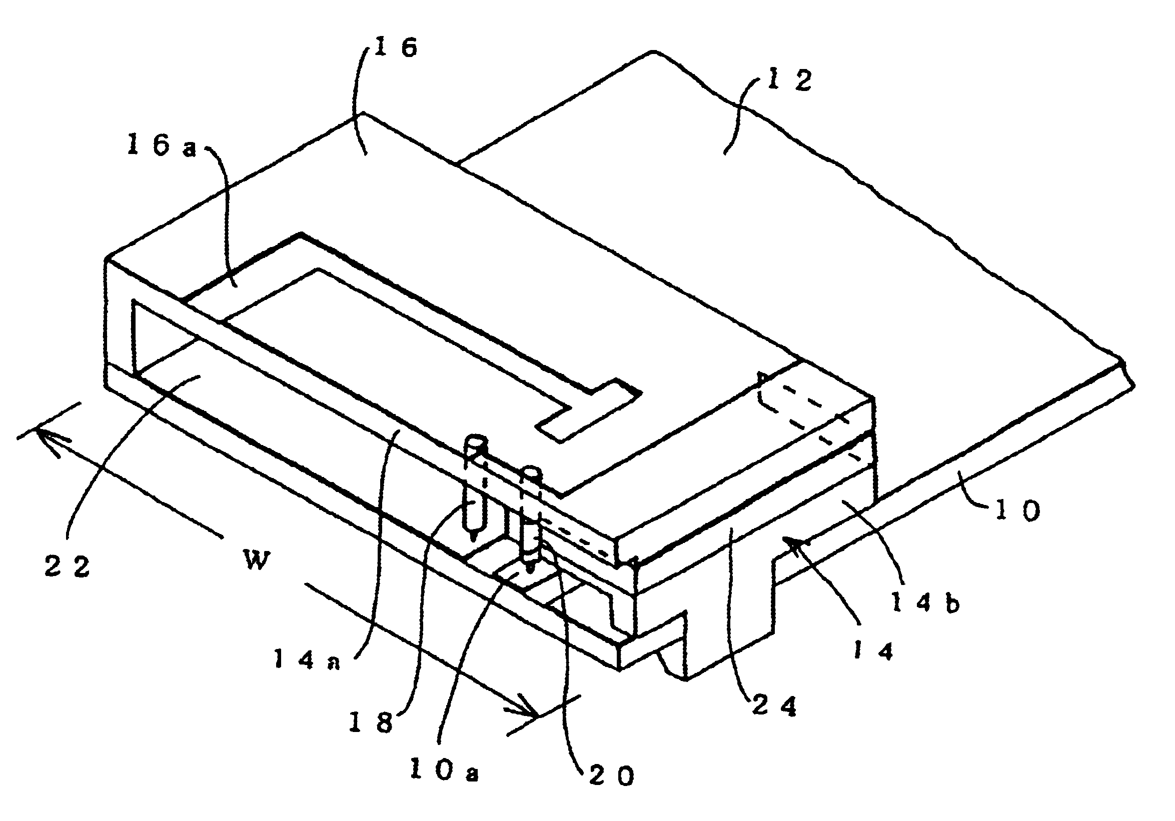
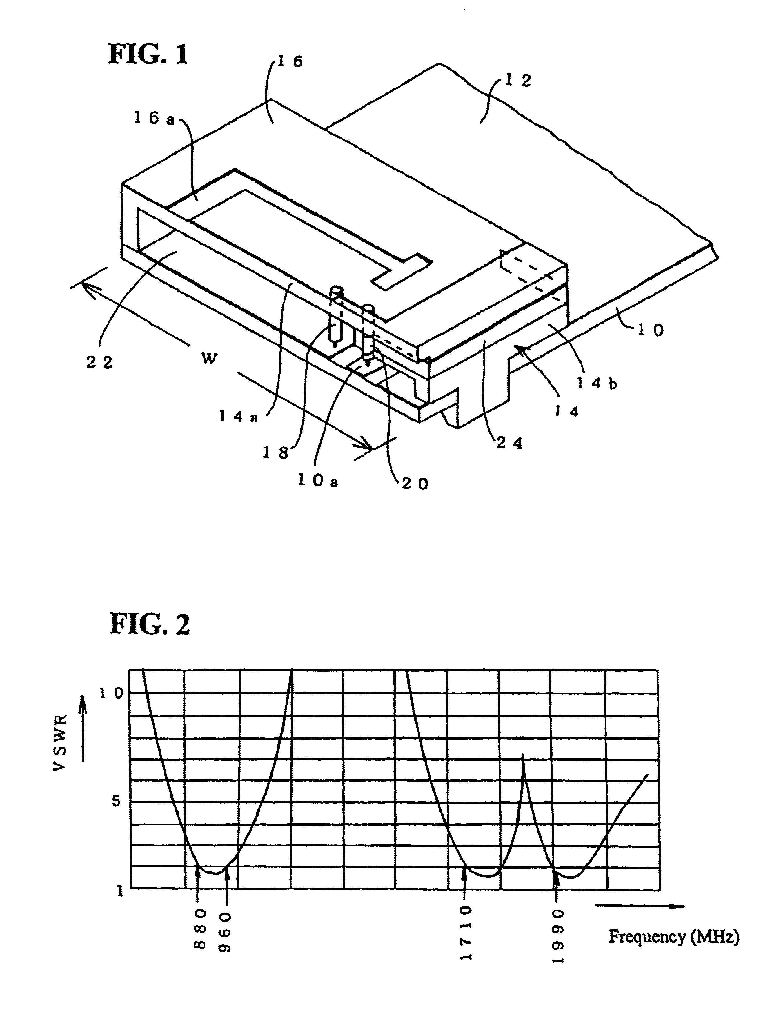
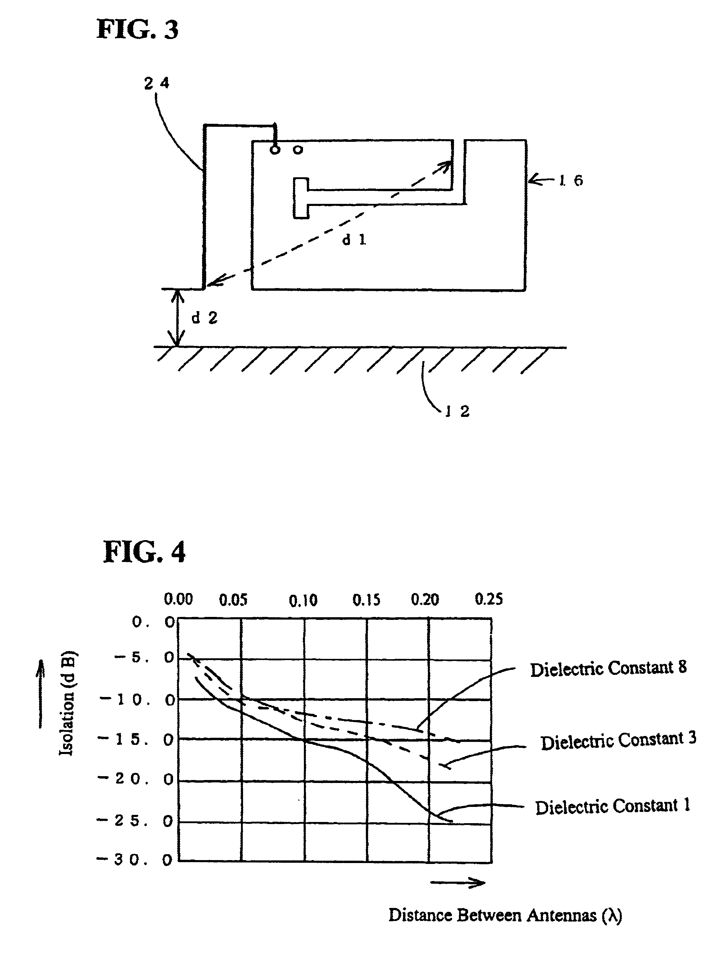
[0055]the broad-band antenna for the mobile communication of the invention having such structure functions as described below. First, the second frequency band at which the second antenna element is resonant and the third frequency band at which the third antenna element 24 is resonant are frequencies so close that part of the frequency bands overlap with each other. When the isolation of the second antenna element and the third antenna element 24 is poor, as shown in FIG. 2, an antiresonant point occurs between the center frequencies of the second and the third frequency bands, and there is a tendency that the VSWR characteristic deteriorates very much. Besides, in the third antenna element 24, a desired antenna characteristic is hard to obtain because of inductive coupling and / or capacitive coupling with respect to the grounding plate 12.

[0056]The present inventors considered these circumstances, and experimentally obtained a distance at which the second antenna element and the th...

sixth embodiment

[0071]In the sixth embodiment, a third antenna element 34 is not provided on the surface of a carrier 14, is formed of a helical coil antenna element, has a base end electrically connected to a feed terminal 20, and is provided to protrude from the carrier 14.

[0072]In the sixth embodiment of the structure as stated above, the third antenna element 34 is provided to protrude from the carrier 14, so that a distance d1 from the end of a second antenna element can be made large, and when the third antenna element 34 is made to protrude toward the side where a circuit board 10 does not exist as shown in FIG. 24, a distance d2 from a grounding plate 12 can also be made large. Then, as compared with the first embodiment, it can be used in a broader band.

[0073]Further, a seventh embodiment of a broad-band antenna for mobile communication of the invention will be described with reference to FIG. 26. FIG. 26 is an outer appearance view of a structure of the seventh embodiment of the broad-ban...

eighth embodiment

[0078]In this eighth embodiment, since the third antenna element 46 is provided at the lower surface of the top plate part 14a, the metal plate 16 can be disposed on the whole upper surface of the carrier 14. Then, the thickness of the top plate part 14a is suitably set, so that the third antenna element 46 can be disposed to be spaced from the second antenna element by a suitable distance. Besides, the third antenna element 46 is not limited to the thin band shape, but may have a terminal shape.

[0079]Incidentally, in the above embodiments, although the description has been made on the assumption that the broad-band antenna for the mobile communication of the invention is incorporated in the chassis of the portable phone, when it is used for a mobile communication equipment other than the portable phone, which does not have a strict dimensional restriction, the third antenna element 24 may be provided on the upper surface of the carrier 14 to be sufficiently spaced from the metal pl...


PUM


Abstract

The present invention provides a broad-band antenna for mobile communication in which a desired antenna characteristic is obtained in plural frequency bands of a portable phone or the like. A metal plate 16 having a suitable shape is disposed on an upper surface of a carrier 14 provided on a circuit board 10, and a first and a second antenna elements functioning as inverted-F antennas respectively resonant at a first frequency band and a second frequency band higher than the former are formed by electrically connecting the metal plate 16 to a grounding plate 12 and the circuit board 10 by an earthing terminal 18 and a feed terminal 20, respectively. A third antenna element 24 having a base end electrically connected to the feed terminal 20 and resonant at a third frequency band higher than the second frequency band is provided on a side surface of the carrier 14, ends of the second antenna element and the third antenna element 24 are disposed to be spaced from each other by a distance of 0.1 wavelength or more of the third frequency band, and the end of the third antenna element 24 is disposed to be spaced from the grounding plate 12 by a distance of 0.01 wavelength or more of the third frequency band. Besides, the third antenna element may be made resonant at a fourth frequency band higher than the third frequency band, and a matching circuit to perform matching for the third frequency band may be provided.

Description

[0001]This application is the national phase under 35 U.S.C. §371 of PCT International Application No. PCT / JP02 / 03915 which has an International filing date of Apr. 19, 2002, which designated the United States of America.TECHNICAL FIELD[0002]The present invention relates to a broad-band antenna for mobile communication, which transmits and receives plural frequency bands for mobile communication such as in a portable phone.BACKGROUND ART[0003]As frequency bands for mobile communication of portable phones, GSM (880 to 960 MHz) and DCS (1710 to 1880 MHz) are used in Europe, AMPS (824 to 894 MHz) and PCS (1850 to 1990 MHz) are used in the United States, and PDC 800 (810 to 960 MHz) and PDC 1500 (1429 to 1501 MHz) are used in Japan. Then, as a built-in antenna of a portable phone, an antenna capable of transmitting and receiving two frequency bands respectively corresponding to areas where the equipment is used is generally used.[0004]An example of a structure of this conventional dual ...

Claims


Application Information

Patent Timeline
Patent Type & Authority Patents(United States)
IPC IPC(8): H01Q9/04H01Q5/00H01Q21/28H01Q21/00H01Q5/10H01Q5/371
CPCH01Q9/0407H01Q5/371H01Q21/30H01Q9/0421H01Q1/24
Inventor OSHIYAMA, TADASHIMIZUNO, HIROTOSHISUZUKI, YUSUKE
Owner YOKOWO CO LTD
Why Eureka
Try Eureka