
Method and system for mode adaptation in wireless communication

a wireless communication and mode adaptation technology, applied in the field of mode adaptation, can solve the problems of inability to adapt to inability to coding techniques and data formats, and inability to achieve the current data rate, etc., and achieve the effect of improving the quality parameter

Inactive Publication Date: 2005-07-26
INTEL CORP
View PDF15 Cites 152 Cited by
  • Summary
  • Abstract
  • Description
  • Claims
  • Application Information

AI Technical Summary

Benefits of technology

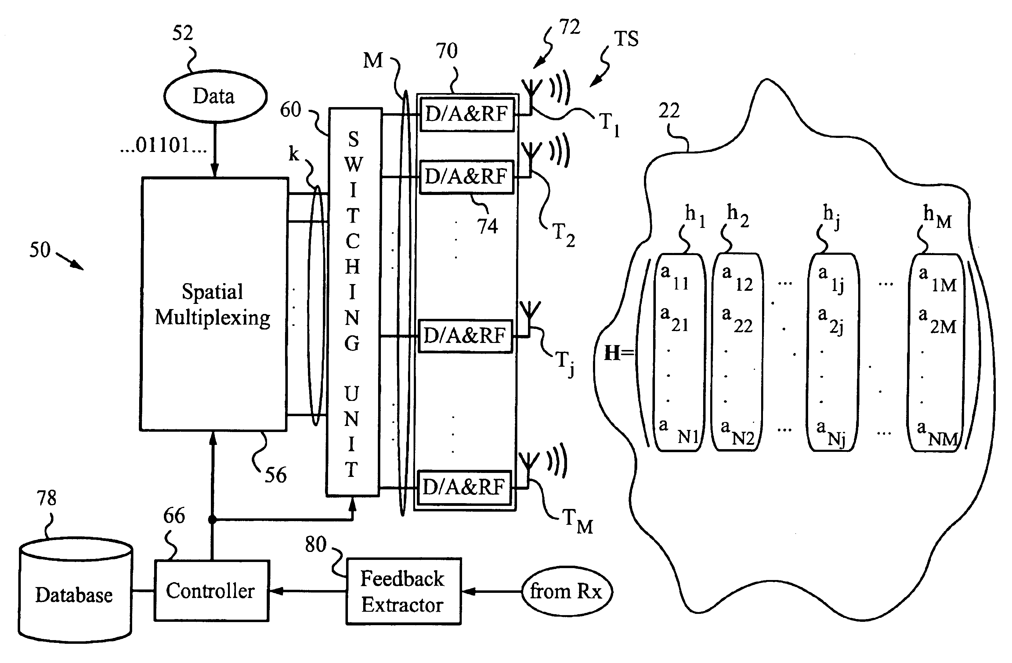
[0026]In still another embodiment, the transmit antennas belong to separate transmit units, e.g., to different base stations. In this case the sub-matrix hj can represent the base station transceiver which is to be deactivated to improve the quality parameter at the receive unit.
[0027]Systems of the invention can be used for spatial multiplexed communications between transmit units with multiple antennas and receive units with multiple antennas, or between separate transceivers, e.g., base stations, and receive units with multiple antennas. The receive unit has a channel estimation block for determining channel descriptor, a mode selection block for receiving the quality parameter, assigning a threshold to the quality parameter, and identifying among the sub-descriptors of the channel descriptor at least one sub-descriptor not meeting the threshold. The receive unit has a feedback unit for sending feedback related to the at least one sub-descriptor to the transmit unit or, as the case may be, to the base stations.
[0028]In case the transmit unit has an antenna array, a controller at the transmit unit receives the feedback and deactivates the corresponding transmit antennas. In case the transmit antennas belong to separate transceivers, a common controller or separate control units can be used to receive the feedback and deactivate the corresponding transceivers or their antennas.

Problems solved by technology

Under altered conditions former data rates, coding techniques and data formats may no longer be feasible.
For example, when channel performance is degraded the transmitted data may experience excessive corruption yielding unacceptable communication parameters.
For instance, transmitted data can exhibit excessive bit-error rates or packet error rates.
In mobile systems, a variety of factors cause signal degradation and corruption.
These include interference from other cellular users within or near a given cell.
Another source of signal degradation is multipath fading, in which the received amplitude and phase of a signal varies over time.
In such environments, the problem is to cleanly extract the signal of the user being tracked from the collection of received noise, CCI, and desired signal portions summed at the antennas of the array.
Still, over time, channel coherence will be lost in FWA systems as well.
However, effective maximization of channel capacity with multiple transmit and receive antennas is not possible only with adaptive modulation and / or coding.
The disadvantage of the beam-forming method taught by Barratt et al., Ottersten et al., and Roy III is that the users have to be spatially well separated and that their spatial signatures have to be known.
Also, the channel information has to be available to the transmit unit ahead of time and the varying channel conditions are not effectively taken into account.
Prior art systems do not teach rules suitable for determining antenna mappings, or, more precisely, antenna selection for varying channel conditions in the spatial multiplexing mode.

Method used


Image

  • Method and system for mode adaptation in wireless communication
  • Method and system for mode adaptation in wireless communication
  • Method and system for mode adaptation in wireless communication

Examples


Embodiment Construction

and the preferred and alternative embodiments is presented below in reference to the attached drawing figures.

BRIEF DESCRIPTION OF THE FIGURES

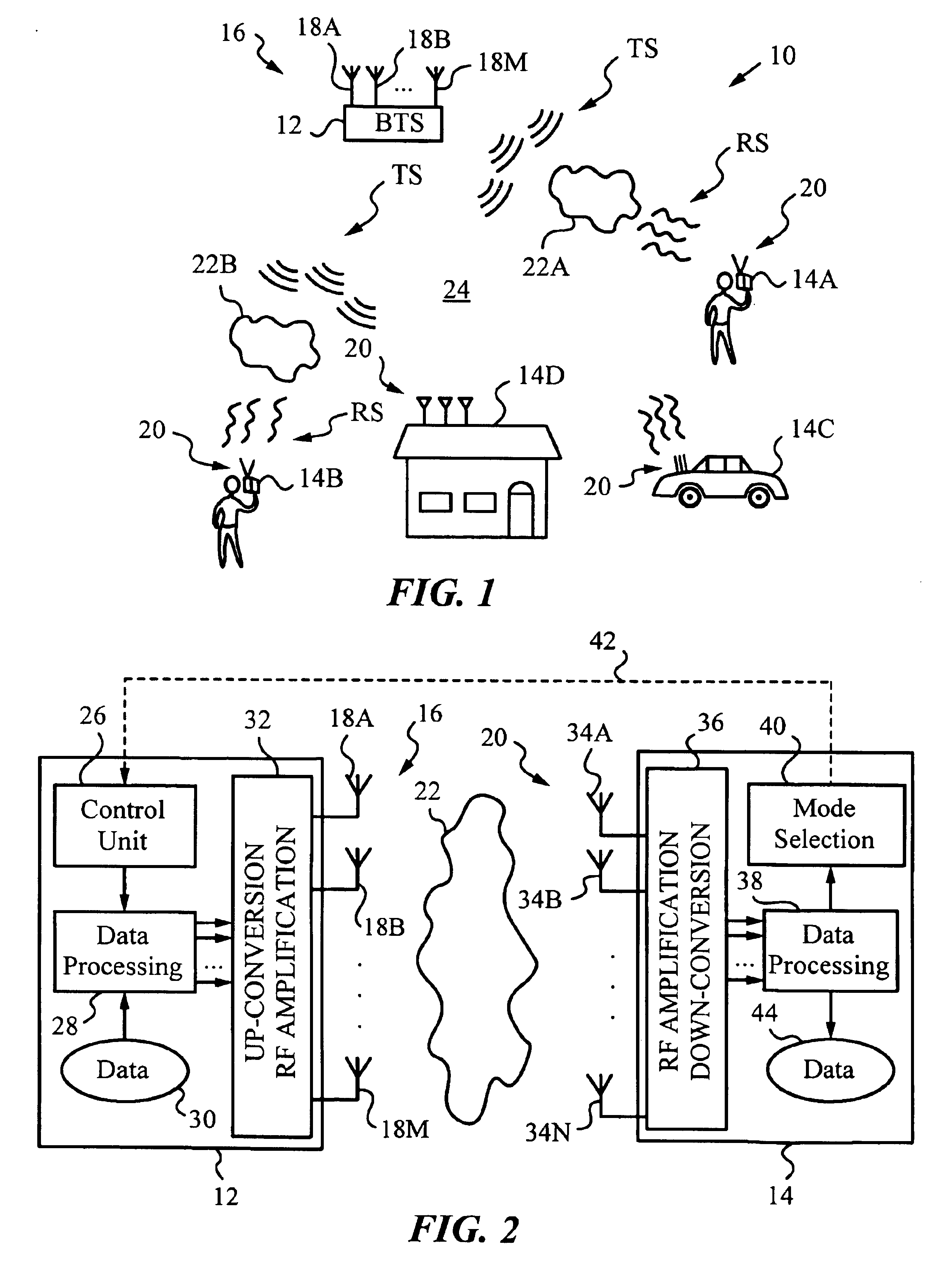
[0031]FIG. 1 is a simplified diagram illustrating a communication system in which the method of the invention is applied.

[0032]FIG. 2 is a simplified block diagram illustrating the transmit and receive units according to the invention.

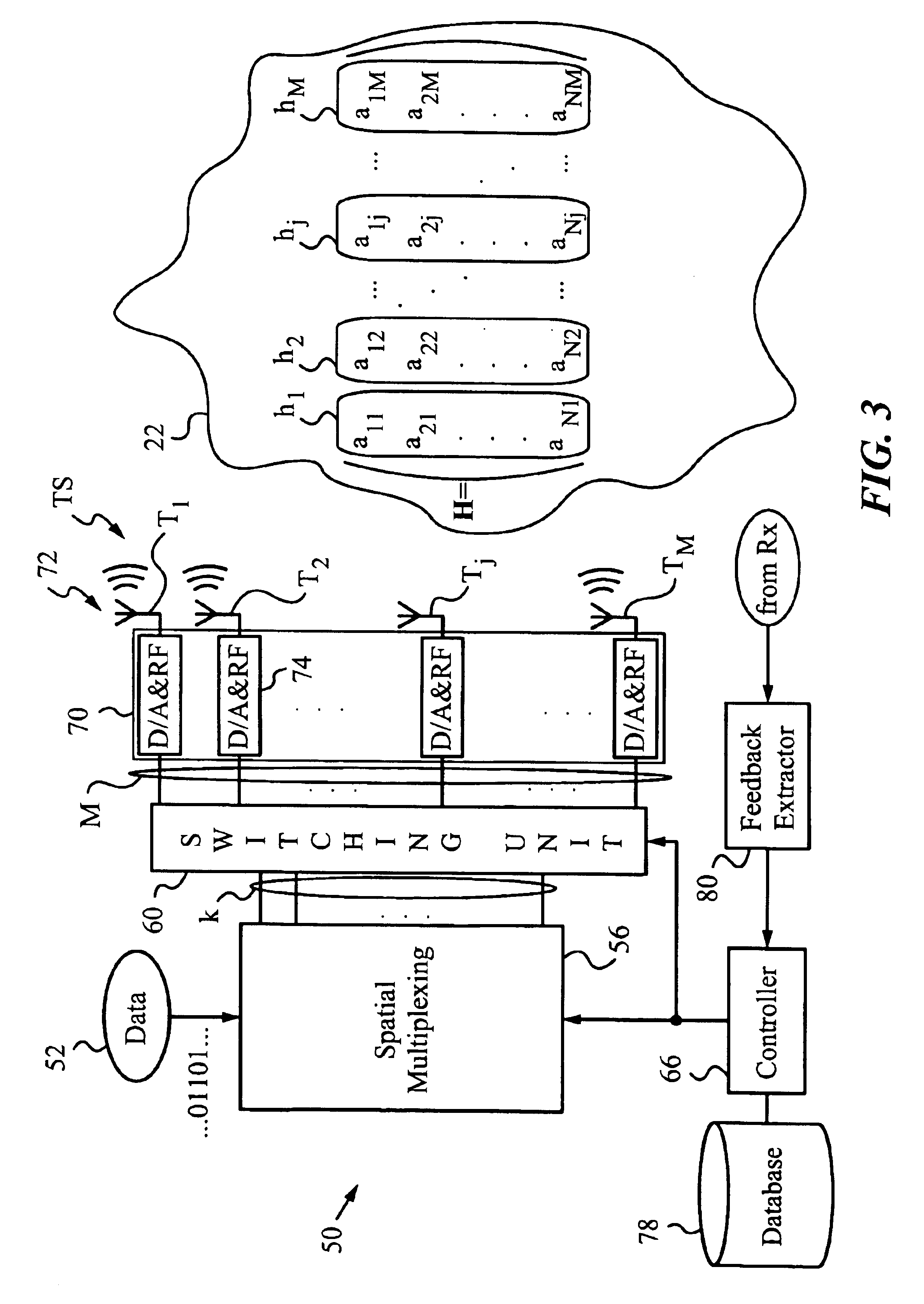
[0033]FIG. 3 is a block diagram of an exemplary transmit unit in accordance with the invention.

[0034]FIG. 4 is a block diagram of a spatial multiplexing block of the transmit unit of FIG. 3.

[0035]FIG. 5 is a block diagram of exemplary receive unit in accordance with the invention.

[0036]FIG. 6. is a schematic illustrating the operations performed on the channel matrix H.

[0037]FIG. 7 is a block diagram of a mode selection block of the receive unit of FIG. 5.

[0038]FIG. 8 is an exemplary flow chart of the method of the invention.

[0039]FIG. 9 is a diagram of another embodiment of the invention.

DETAILED DESCRIPTION

[004...


PUM


Abstract

A method and system for selective mode adaptation for transmitting data by spatial multiplexing applicable in communications systems with a transmit unit having multiple transmit antennas or multiple transmit units and a receive unit having multiple receive antennas. A channel descriptor, such as channel matrix H or a channel matrix filter , with has sub-descriptors corresponding to the transmit antennas is determined and a quality parameter, such as signal-to-interference and noise ratio, signal-to-noise ratio or power level are chosen. The quality parameter is assigned a threshold and the sub-descriptor or sub-descriptors whose quality parameters do not meet the threshold are identified and deactivated.

Description

RELATED APPLICATIONS[0001]This patent application is a continuation-in-part of patent application Ser. No. 09 / 464,372 filed on Dec. 15, 1999, now U.S. Pat. No. 6,351,499 and of patent application Ser. No. 09 / 585,948 filed on Jun. 2, 2000 now U.S. Pat. No. 6,298,092 which are herein incorporated by reference.FIELD OF THE INVENTION[0002]The present invention relates generally to wireless communication systems and methods, and more particularly to mode adaptation including selection of transmit antennas in transmit units employing multiple antennas for spatial multiplexing.BACKGROUND OF THE INVENTION[0003]Wireless communication systems serving stationary and mobile wireless subscribers are rapidly gaining popularity. Numerous system layouts and communications protocols have been developed to provide coverage in such wireless communication systems.[0004]Wireless communications channels between transmit and receive devices are inherently variable and their quality fluctuates.[0005]Specif...

Claims


Application Information

Patent Timeline
Patent Type & Authority Patents(United States)
IPC IPC(8): H01Q3/26H01Q1/24H04L1/06H04L1/00H04B7/04H04L1/02H04B7/08H04B7/06
CPCH01Q1/246H01Q3/2605H04B7/0669H04B7/0697H04B7/084H04B7/0857H04L1/0001H04L1/0003H04L1/0009H04L1/0026H04L1/06H04L1/0618H04B7/0673
Inventor SAMPATH, HEMANTHSEBASTIAN, PEROOR K.PAULRAJ, AROGYASWAMI J.
Owner INTEL CORP
Learn More