
Method and apparatus for lay flat control in an extruded film production line

a technology of extruded film and control method, applied in the direction of two-way working system, electric controller, instrument, etc., can solve the problem of difficult (but not impossible) use of optical sensors, and achieve the effect of improving lay-flat control and improving ability

Inactive Publication Date: 2005-07-26
JOSEPH DANIEL R
View PDF3 Cites 4 Cited by
  • Summary
  • Abstract
  • Description
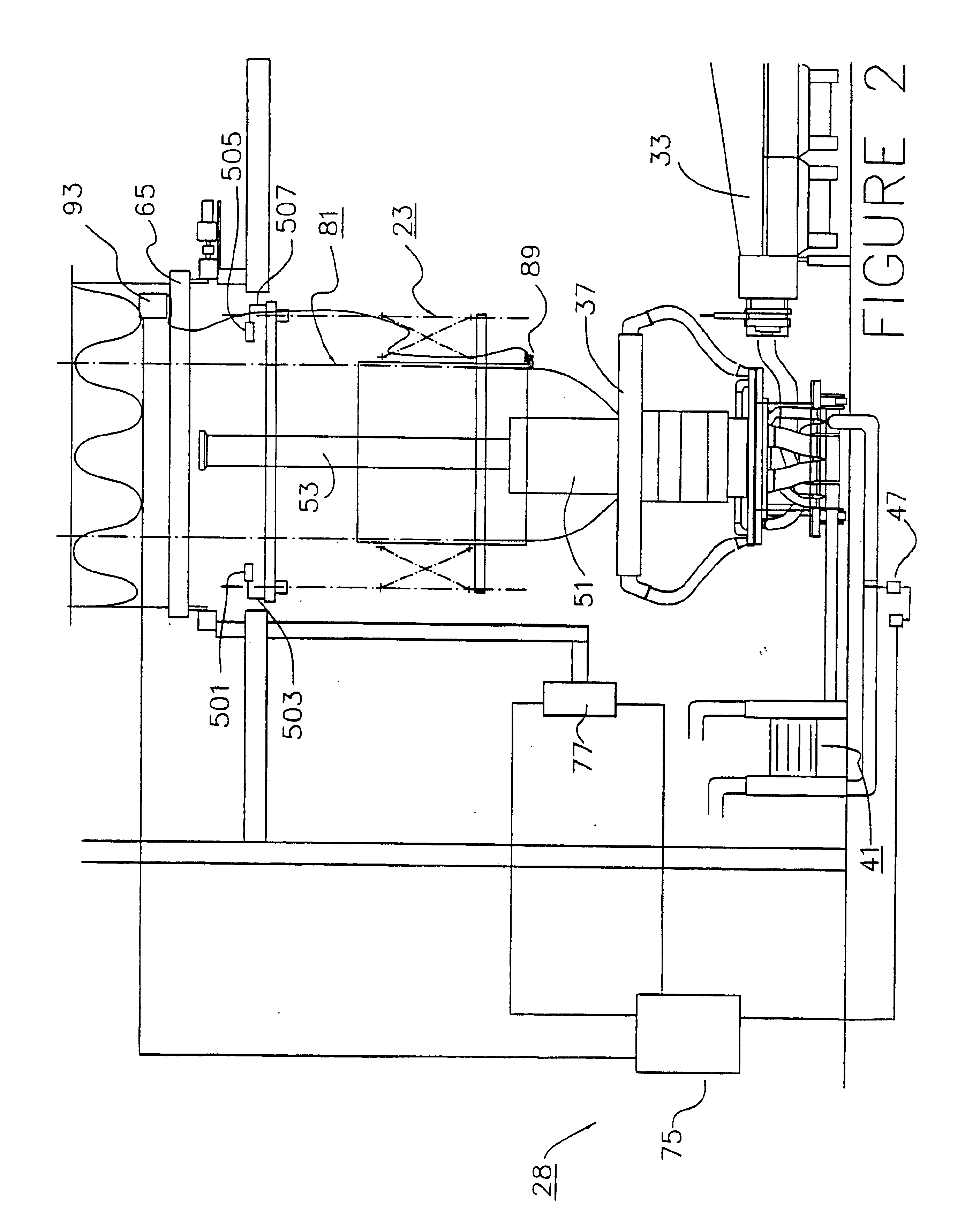
  • Claims
  • Application Information

AI Technical Summary

Benefits of technology

[0008]It is one objective of the present invention to provide a substantially improved ability to keep blown film product width within established specifications. This invention provides improved lay-flat control by adding a second feedback control loop, in addition to, and or supplementation of, the primary control feedback loop which is utilized to control the extrusion and cooling process.
[0009]This additional and / or supplemental control loop of the present invention measures actual bubble diameter, preferably (but not necessarily) utilizing acoustic sensors, and feeds back this information to one or more controllers. Preferably the controller is the one which is utilized to perform the calculations and control operations of the primary control loop for expanding and cooling the extruded film tube. The sensed diameter data is compared against an operator established set point. In the preferred embodiment, the resulting error is injected into the Internal Bubble Cooling system (the “IBC”) to provide a correction effect. In the preferred embodiment, this is in fact directly added as an input to the primary control loop.
[0012]One additional problem of the prior art is resolved by the present invention. IBC performance depends on stable airflow sources to maintain a stable bubble. Therefore, disturbances can result in changes in the final product width. In particular, rotating or oscillating dies use moving air chambers that can induce a disturbance in the airflow as a result of uneven airflow in the chamber. In the present invention, the variation in product diameter resulting from the airflow changes that occur because of imbalances in the rotating chamber can be significantly reduced.
[0013]In accordance with the preferred embodiment of the present invention, one or more sensors are positioned in a different horizontal plane from the IBC control sensors. Preferably, these sensors are also placed in a different circumferential position than the primary control loop sensors. In this patent, these sensors are called “lay-flat” sensors to distinguish them from the IBC sensors. In the preferred embodiment, the placing the lay-flat sensors in a horizontal plane vertically above the IBC sensors provides optimum results. The purpose of these sensors is to provide a measurement of the actual bubble diameter from which the final lay-flat dimension can be calculated from a simple formula (lay-flat equals pi multiplied by the sensed diameter divided by two).

Problems solved by technology

It may however be difficult (but not impossible) to use optical sensor since the sensor response would be dependent on the color of the extruded tube.

Method used


Image

  • Method and apparatus for lay flat control in an extruded film production line
  • Method and apparatus for lay flat control in an extruded film production line
  • Method and apparatus for lay flat control in an extruded film production line

Examples


Embodiment Construction

[0040]Although the invention has been described with reference to a particular embodiment, this description is not meant to be construed in a limiting sense. Various modifications of the disclosed embodiments as well as alternative embodiments of the invention will become apparent to persons skilled in the art upon reference to the description of the invention. It is therefore contemplated that the appended clams will cover any such modifications or embodiments that fall within the scope of the invention.

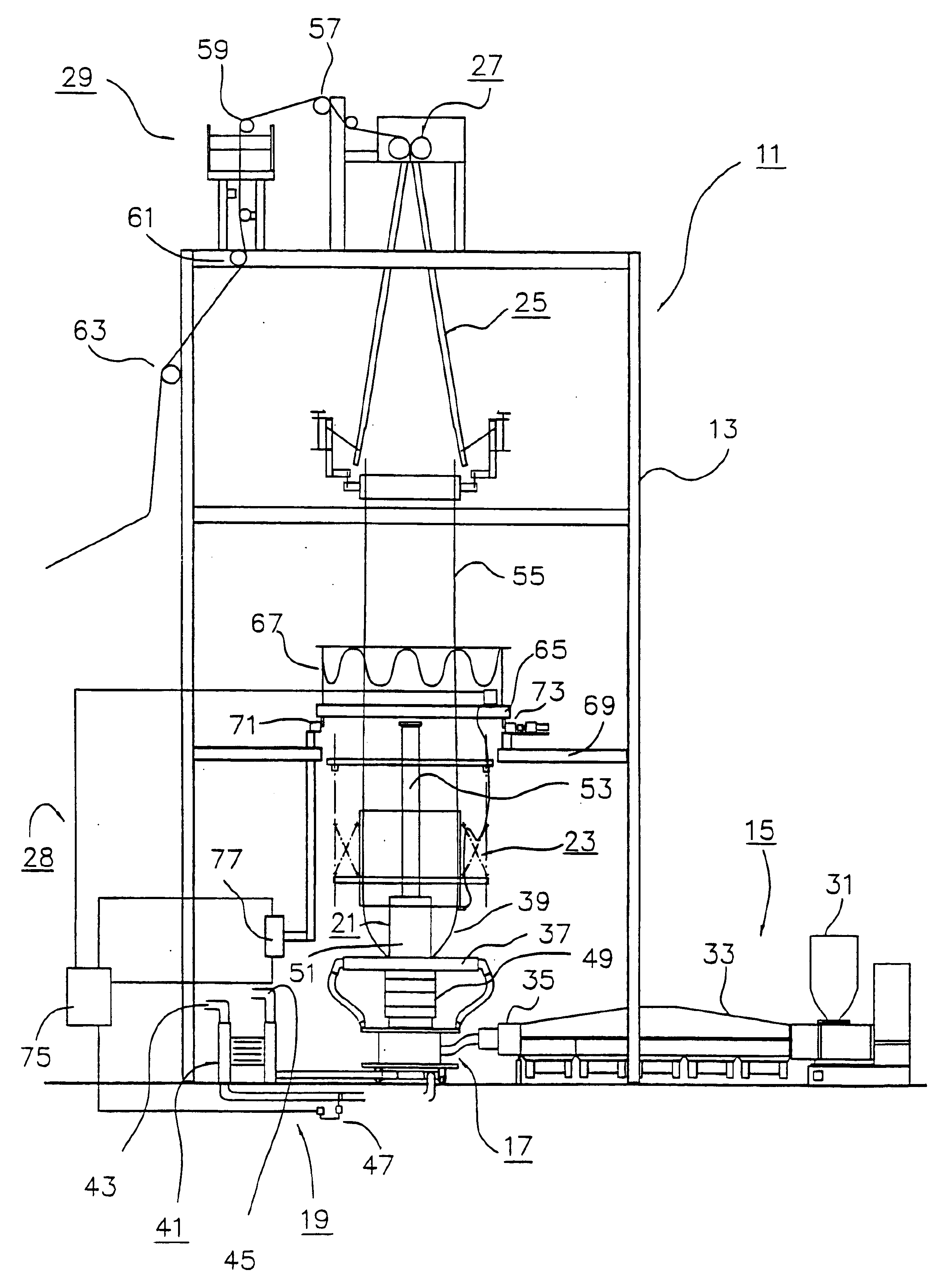
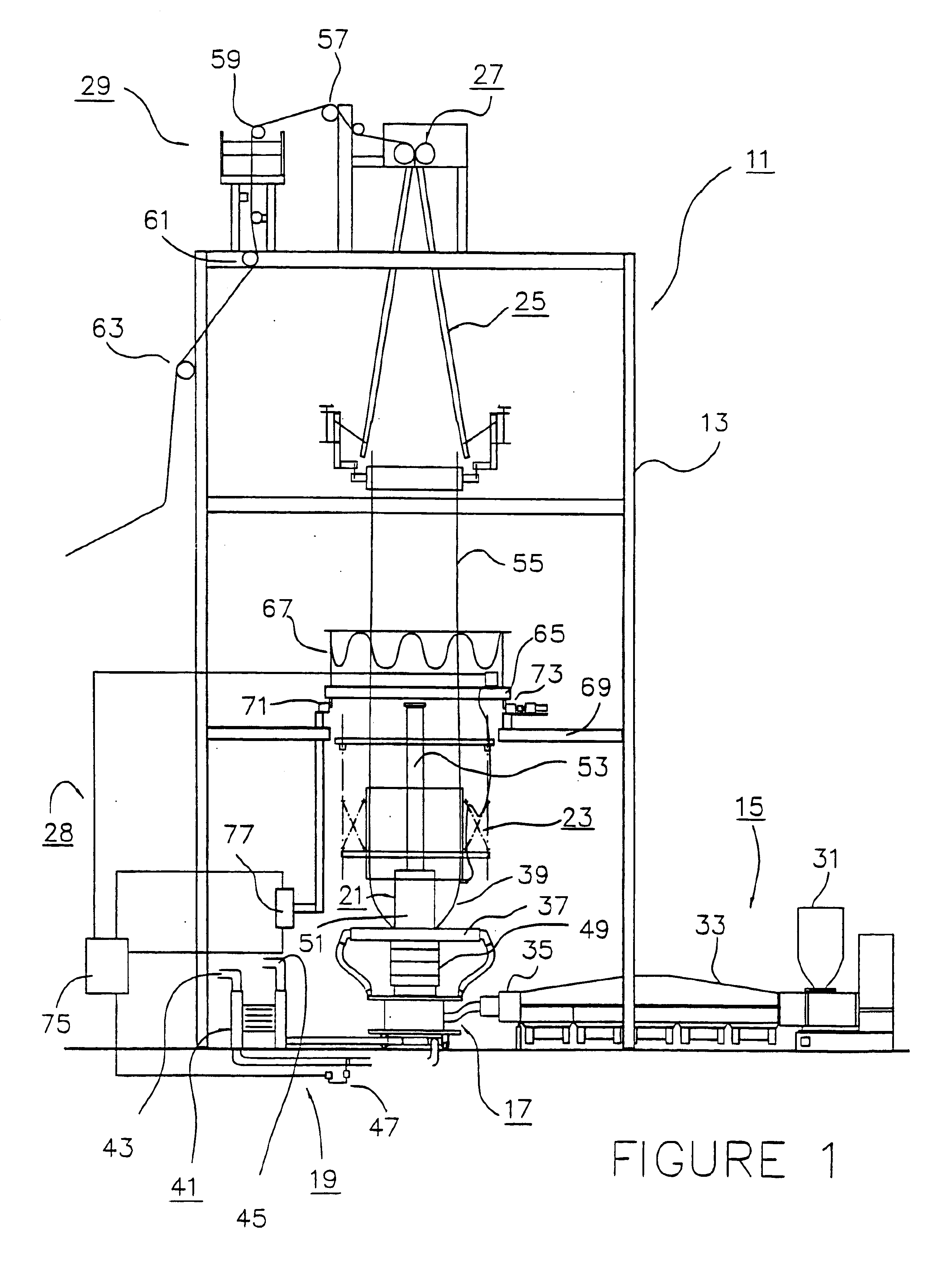
[0041]FIG. 1 is a view of blown film extrusion line 11, which includes a number of subassemblies which cooperate to produce plastic bags and the like from plastic resin. The main components include blown film tower 13, which provides a rigid structure for mounting and aligning the various subassemblies, extruder subassembly 15, die subassembly 17, blower subassembly 19, stack 21, sizing cage 23, collapsible frame 25, nips 27, control subassembly 28 and rollers 29.

[0042]Plastic granu...


PUM

PropertyMeasurementUnit
distanceaaaaaaaaaa
diameteraaaaaaaaaa
pressureaaaaaaaaaa

Abstract

An apparatus for producing an extruded film tube and supplying said tube to a collapsing and roller assembly includes a die for extruding a molten material in the form of a tube which is in a molten state below a frost line and in a solid state above the frost line. A blower system supplies and exhausts cooling air to and from an interior portion of the tube, and is regulated by a valve. At least two sensors are provided, one below the frost line for sensing the position of said tube, and one located proximate the tube in a position above said frost line. The upper sensor is used for sensing the position of the tube prior to collapsing and flattening it. A controller receives feedback signals from both sensors and controls operation of the valve.

Description

PROVISIONAL PRIORITY CLAIM[0001]This is a continuation of prior application Ser. No. 09 / 761,035 filed 16 Jan. 2001, for “Method And Apparatus For Lay Flat Control In An Extruded Film Production Line”, which is now U.S. Pat. No. 6,592,786.BACKGROUND OF THE INVENTION[0002]1. Field of the Invention[0003]The present invention relates in general to an extruded film processing system, and in particular to control systems utilized in extruded film processing systems.[0004]2. Description of the Prior Art[0005]Blown film extrusion lines are used to manufacture plastic bags and plastic sheets. A molten tube of plastic is extruded from an annular die, and then stretched and expanded to a larger diameter and a reduced radial thickness by the action of overhead nip rollers and internal air pressure. Typically, ambient air is entrained by one or more blowers. The ambient air provides a cooling medium, which absorbs heat from the molten material. This speeds up the change in state from a molten ma...

Claims


Application Information

Patent Timeline
Patent Type & Authority Patents(United States)
IPC IPC(8): B29C47/00B29C47/90B29C47/92H04N7/173H04N7/16B29C48/10B29C48/355B29C48/90B29C48/92
CPCB29C47/0026B29C47/903B29C47/92H04N7/17318H04N7/17336H04N21/222H04N21/23106H04N21/252H04N21/25891H04N21/44222H04N21/4524H04N21/466B29C47/0057B29C47/0059B29C47/34B29C2947/92123B29C2947/92209B29C2947/92295B29C2947/92514B29C2947/926B29C2947/92628B29C2947/92647B29C2947/92657B29C2947/92809B29C2947/92923B29C48/92B29C2948/92209B29C48/10B29C48/0018B29C48/0019B29C48/355B29C48/913B29C48/903B29C2948/92123B29C2948/92295B29C2948/92514B29C2948/926B29C2948/92628B29C2948/92647B29C2948/92657B29C2948/92809B29C2948/92923
Inventor JOSEPH, DANIEL R.
Owner JOSEPH DANIEL R
Learn More