
Method for preventing magnetic damage to a GMR head during back-end processing

Inactive Publication Date: 2005-08-02
HEADWAY TECH INC
View PDF9 Cites 3 Cited by
  • Summary
  • Abstract
  • Description
  • Claims
  • Application Information

AI Technical Summary

Benefits of technology

[0009]Accordingly, it is a first object of this invention to provide a method of improving GMR (and, generally, MR) product yields by restoring magnetic biasing during and subsequent to back-end processing to within specifications established prior to back-end processing.
[0010]It is a second object of the present invention to provide a novel fixture to support GMR assemblies during back-end processes such as row and slider manufacturing operations including lapping, which fixture enables the use of external magnetic fields to stabilize the transverse biasing in said assemblies.
[0011]The objects stated above will be achieved by applying the proper magnetic field to the GMR head (or other assembly, generically called the “workpiece” hereinafter) during back-end processing. The field can be provided by permanent or electromagnets which can be external to the workpiece and mounted in a fixture as discussed below, or incorporated within the head structure itself. The magnitude and direction of the field is such that the desired (ie., pre-processing) state of transverse bias is a state of minimum potential energy. More specifically, the direction of the field should be parallel to the desired exchange field provided by the antiferromagnetic (AFM) pinning layer which pins the transverse biasing layer. This field will hereinafter be referred to as the “stabilizing field.” Because the AFM structure is situated in a state of minimum potential energy, it can resist disturbances such as mechanical stress, electrical shock, temperature elevation and stray magnetic fields. Consequently, the transverse bias of the GMR structure is less likely to change.

Problems solved by technology

The heads, themselves, are small and delicate and subject to various types of damage during the back-end processing steps.
Another concern during back-end processing is that the lapping process can proceed beyond the desired limits and damage the active surfaces of the GMR head.
None of the methods discussed above address the problem of possible adverse affects of back-end processing to the magnetic properties of the GMR head.
In back-end processing, the lapping process produces stresses and even plastic deformations within the wafer as an unavoidable part of stock removal.
These stresses cause both biases to change, particularly when combined with other disturbances such as stray magnetic fields, elevated temperatures and ESD induced currents.
As a result, the final GMR product can have its biases altered in a random and uncontrollable fashion, adversely affecting product yields.
While the longitudinal bias can be restored to its pre-processing state with relative ease, restoration of the transverse bias cannot be accomplished economically either during or after the processing.

Method used


Image

  • Method for preventing magnetic damage to a GMR head during back-end processing
  • Method for preventing magnetic damage to a GMR head during back-end processing
  • Method for preventing magnetic damage to a GMR head during back-end processing

Examples


first preferred embodiment

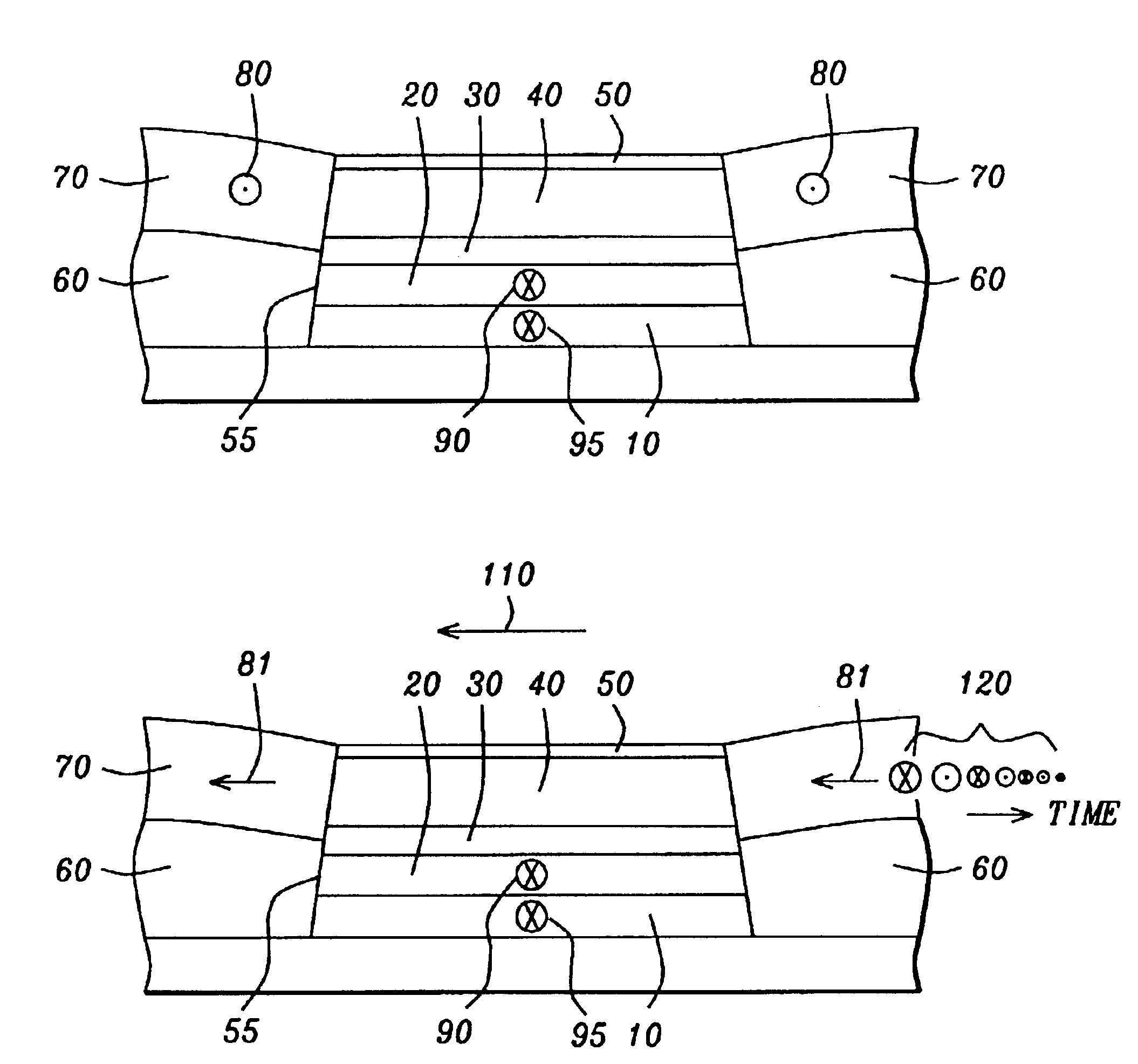
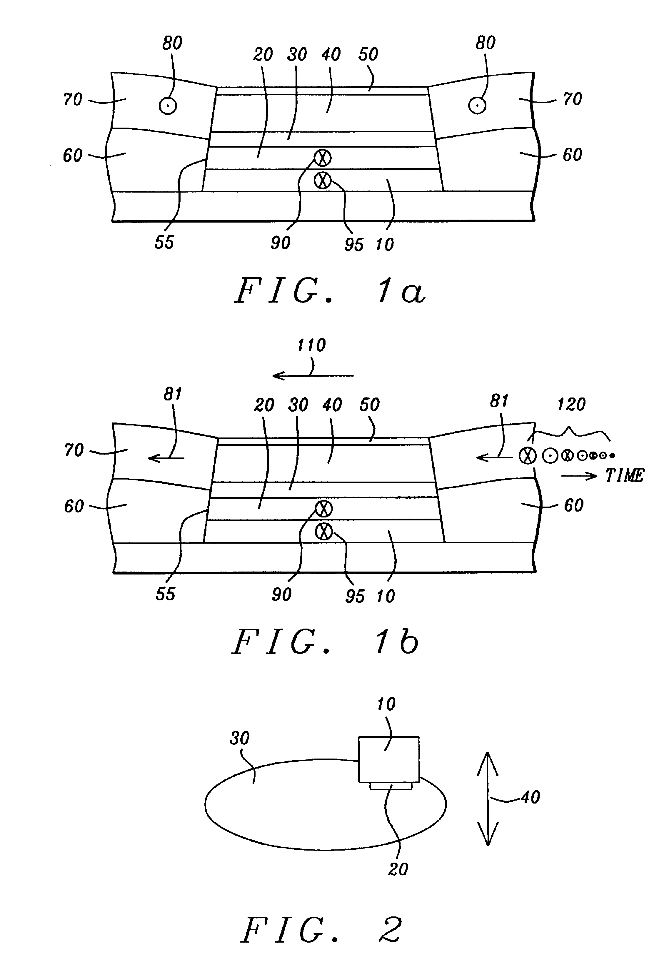
[0023]Referring first to FIG. 1a, there is shown a schematic cross-sectional view of the layer structure of a typical prior-art type GMR read head in the plane of its air-bearing surface (ABS). There is shown the antiferromagnetic (AFM) pinning layer (10), the transverse biasing layer that is the ferromagnetic pinned layer (20) formed on the AFM layer and pinned by the AFM layer, a non-magnetic spacer layer (30) formed on the pinned layer, the ferromagnetic free layer (40) formed on the spacer layer and a capping layer (50). The lateral edges (55) of the layers are shaped so that conducting lead layers (60) and longitudinal biasing layers (70) can be can be deposited and abutted against them as shown in the figure. The figure is both schematic and exemplary. Other configurations of MR and GMR read heads, such as those having laminated free and / or pinned layers, can be equally well treated with the method to be described.

[0024]The diagram also shows the novel magnetization direction ...

second preferred embodiment

[0027]Referring now to FIG. 2, there is shown a schematic diagram of the fixture of the second preferred embodiment (10) holding a secured workpiece (20) against a lapping plate (30). The workpiece is typically a “row bar”, ie., a section of wafer containing multiple GMR head assemblies. The stabilizing magnetic field is shown as a double headed arrow (40), indicating its direction and two possible senses. It is to be noted that the fixture may be used in a lapping process or it may be used in other processes in which a workpiece is to be securely mounted during processing.

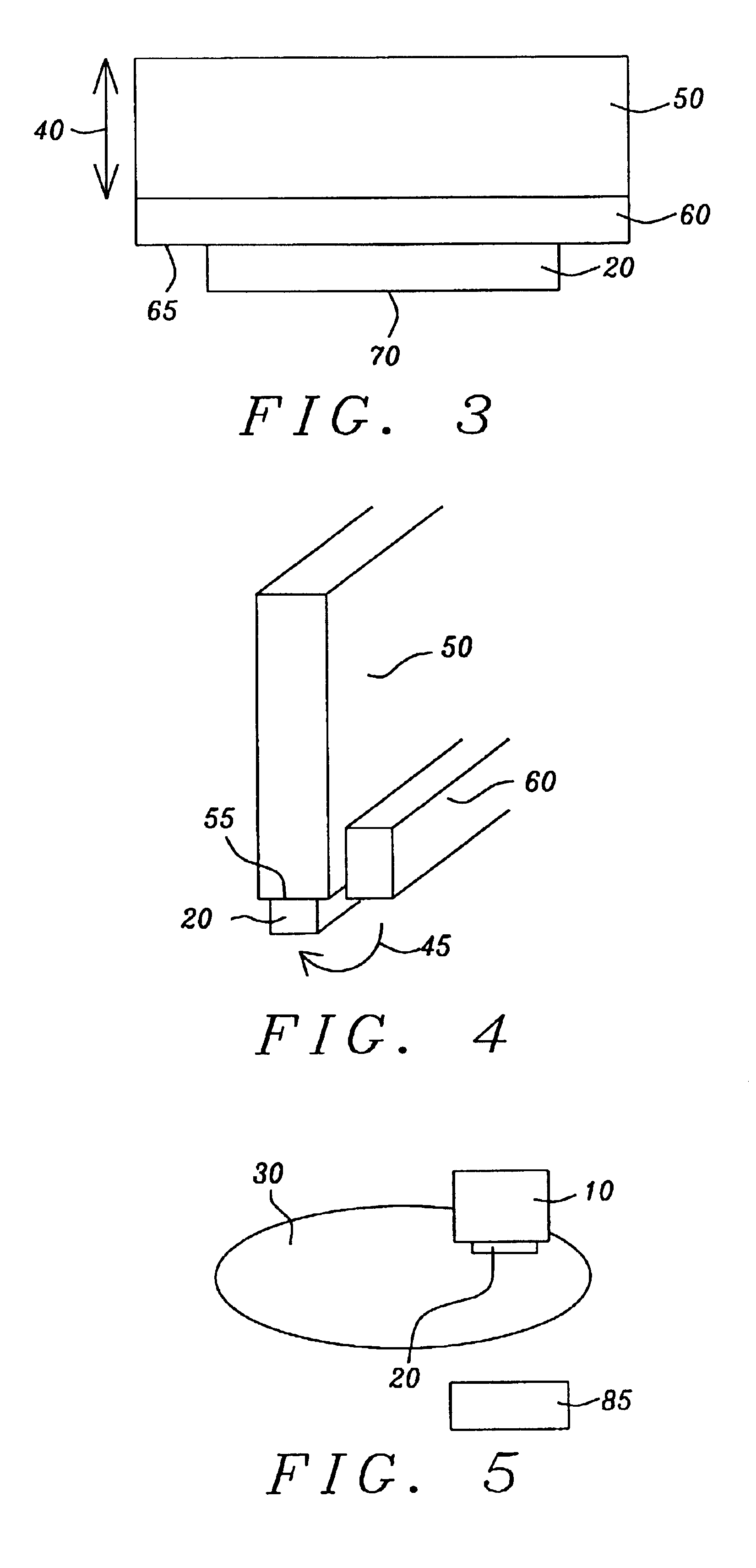
[0028]Referring next to FIG. 3, there is shown a somewhat more detailed schematic illustration of the fixture ((10) of FIG. 2), showing that the fixture comprises a first portion, which is a non-magnetic or soft magnetic portion (50), to which is attached a second portion, which is a magnetic portion (60), which can be a permanent magnet (hard magnetic material) or an electromagnet. A ceramic magnetic material, pr...


PUM

PropertyMeasurementUnit
Timeaaaaaaaaaa
Auxiliary magnetic fieldaaaaaaaaaa

Abstract

A method is provided for preserving the transverse biasing of a GMR (or MR) read head during back-end processing. In a first preferred embodiment, the method comprises magnetizing the longitudinal biasing layers of the read head in a transverse direction, so that the resulting field at the position of the transverse biasing layer places it in a minimum of potential energy which stabilizes its direction. The field of the longitudinal biasing layer is then reset to the longitudinal direction in a manner which maintains the transverse biasing direction. In a second embodiment, a novel fixture for mounting the read head during processing includes a magnetic portion which stabilizes the transverse bias of the read head. The two methods may be used singly or in combination.

Description

BACKGROUND OF THE INVENTION[0001]1. Field of the Invention[0002]This invention relates generally to “back-end” processing of GMR read heads, including the processing of assemblies containing GMR read heads, and particularly to a method of preventing damage to the transverse biasing of the GMR read heads by process induced stresses and by external magnetic fields that may be present during such processing.[0003]2. Description of the Related Art[0004]GMR (giant magneto-resistive) and MR (magneto-resistive) heads and slider assemblies are formed on wafers in arrays of complete, already magnetized units, which must then be subjected to additional, so-called “back-end” process steps, such as separation of the array into individual units and lapping each unit to an acceptable degree of smoothness. An example of how at least a substantial portion of such “back-end” processing proceeds is provided by Sasaki et at. (U.S. Pat. No. 6,374,479), who teach a method of slicing the wafer into rows ...

Claims


Application Information

Patent Timeline
IPC IPC(8): H01F10/00H01F10/32G11B5/39G11B5/00G11B5/31
CPCB82Y10/00G11B5/3169G11B5/3173G11B5/3903H01F10/3268B82Y25/00Y10T29/49048G11B5/3163G11B5/3932G11B2005/0008G11B2005/3996Y10T29/49021Y10T29/4905Y10T29/49041Y10T29/49046Y10T29/49037Y10T29/49034Y10T29/49036Y10T29/49052
Inventor GUO, YIMINZHU, LI-YAN
Owner HEADWAY TECH INC
Features
  • Generate Ideas
  • Intellectual Property
  • Life Sciences
  • Materials
  • Tech Scout
  • Unparalleled Data Quality
  • Higher Quality Content
  • 60% Fewer Hallucinations
Learn More