Drying apparatus

Inactive Publication Date: 2005-08-02
DYSON TECH LTD
View PDF7 Cites 18 Cited by
  • Summary
  • Abstract
  • Description
  • Claims
  • Application Information

AI Technical Summary

Benefits of technology

[0004]It is therefore an object of the present invention to provide drying apparatus capable of operating on the principle of reduced pressure so as to evaporate water vapour from articles at a temperature lower than 100° C. and which is more cost-effective than previously proposed arrangements. It is another object of the invention to provide drying apparatus which is suitable for use in the domestic environ

Problems solved by technology

The disadvantages of these methods include the fact that the articles to be dried are often subjected to high temperatures if a particularly fast drying time is required.
In the case of clothes dryers, this can damage the fabric and, in the case of dishwashers, the crockery becomes too hot to handle as soon as the washing and drying cycle h

Method used


Image

  • Drying apparatus
  • Drying apparatus
  • Drying apparatus

Examples


first embodiment

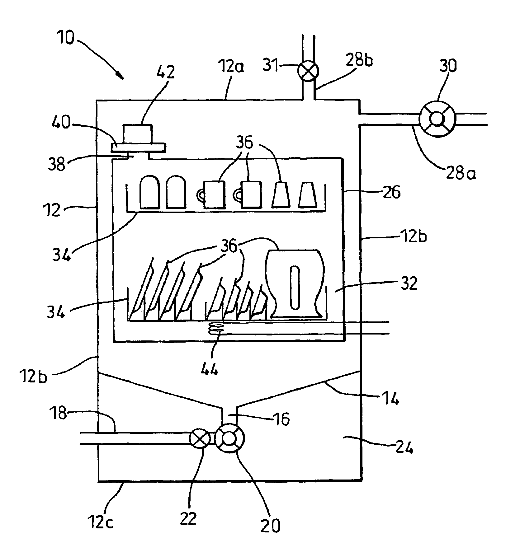
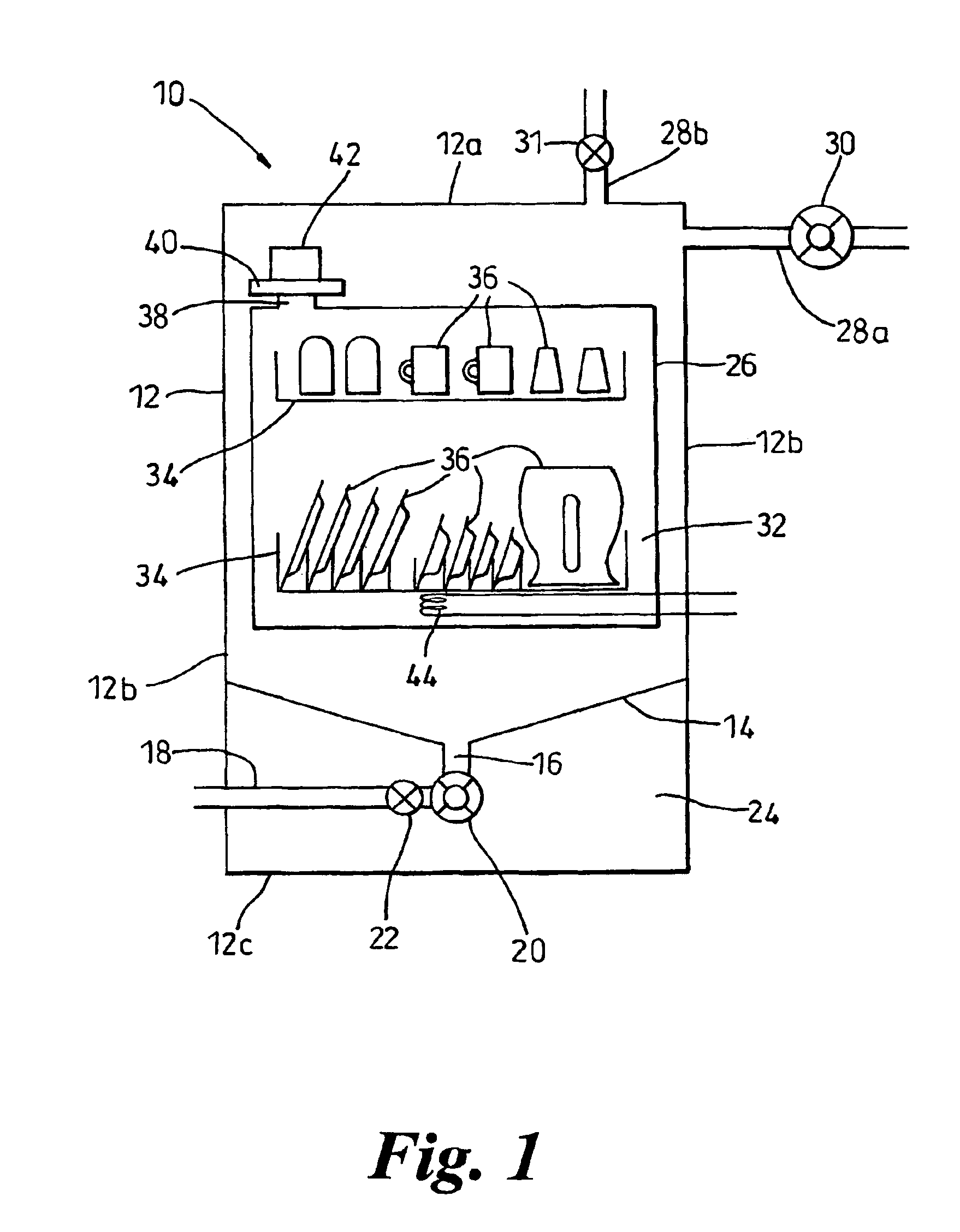
[0031]the invention is illustrated in FIG. 1. In FIG. 1, the drying apparatus according to the invention takes the form of a dishwasher 10. The dishwasher 10 comprises an outer casing 12 having an upper wall 12a, side walls 12b and a base 12c. Suspended between the side walls 12b and sealingly attached thereto, is a tray 14 which is inclined downwardly towards an outlet 16. The outlet 16 is connected to a discharge pipe 18 which leads out of the dishwasher 10 and includes means (not shown) for connecting the discharge pipe 18 to a suitable drain for removing waste water from the dishwasher 10. A pump 20 and a one-way, non-return valve 22 are arranged between the outlet 16 and the discharge pipe 18 for reasons which will be explained below. The pump 20 and the non-return valve 22 are located and housed in a lower chamber 24 delimited by the tray 14, the base 12c and the lower portions of the side walls 12b.

[0032]An upper chamber 26 is delimited by the tray 14, the upper wall 12a and...

second embodiment

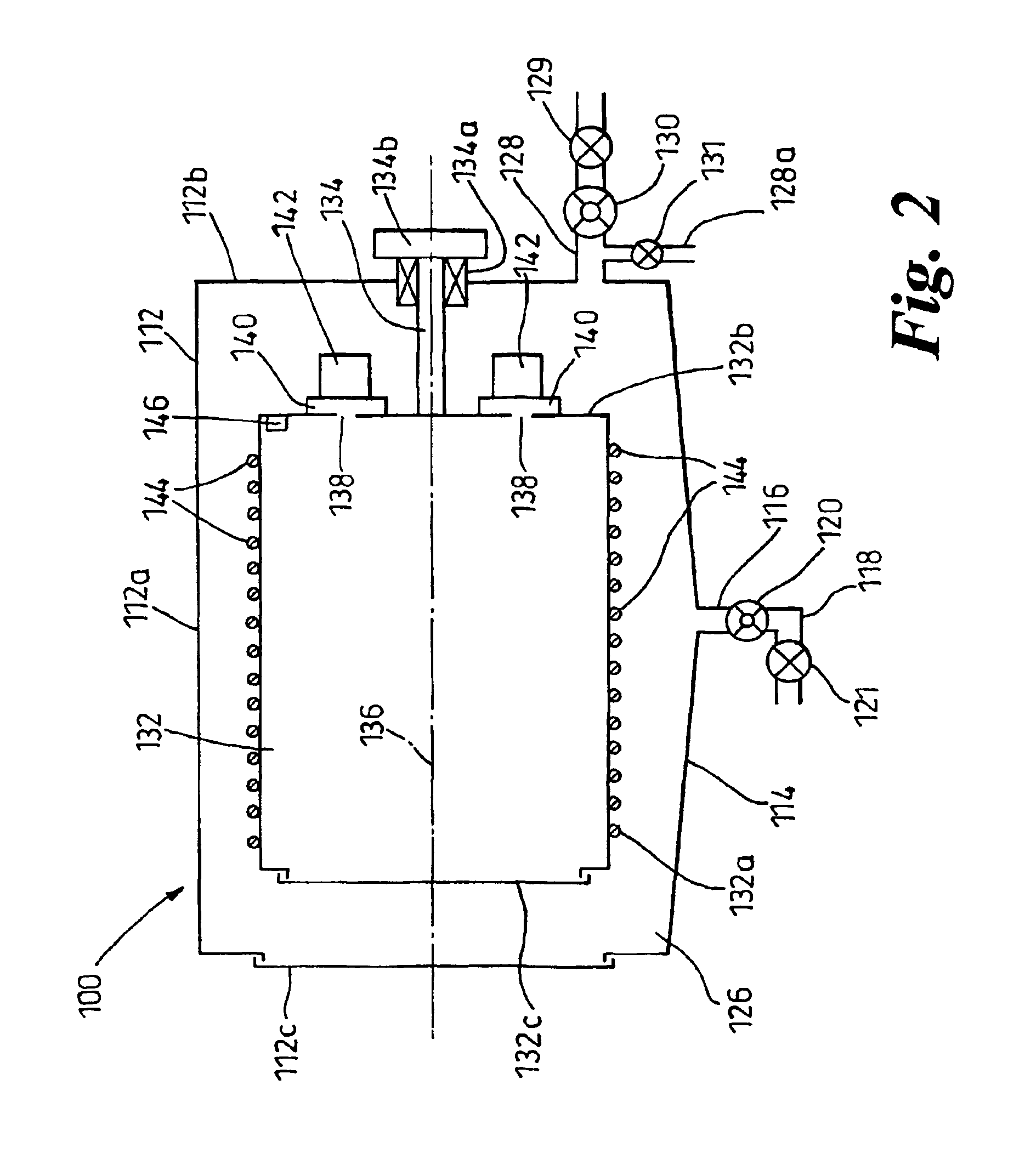
[0040]apparatus according to the invention is illustrated in FIG. 2. In this embodiment, the apparatus takes the form of a tumble dryer or clothes dryer 100. The clothes dryer 100 has an outer casing 112 which may be generally cylindrical in shape. The outer casing 112 has a cylindrical wall 112a, a rear wall 112b and a door 112c arranged opposite the rear wall 112b. The door 112c is hinged so as to be openable so as to allow access to the interior of the clothes dryer 100. Appropriate seals are provided around the door 112c in order to allow the interior of the clothes dryer 100 to be evacuated as will be described below. The lower portion of the cylindrical wall 112a is shaped in the manner of a sump 114 and inclined towards an outlet 116. As described above, the outlet 116 is connected to a discharge pipe 118 with a pump 120 located therebetween and a one-way, non-return valve 119 located in the discharge pipe 118.

[0041]An outer chamber 126 is defined and delimited by the outer c...

fourth embodiment

[0060]FIGS. 4a and 4b illustrate the invention. In this embodiment, the drying apparatus is, once again, a clothes dryer 300 having an outer casing 312. The outer casing 312 consists of a generally cylindrical wall 312a, a rear wall 312b and a door 312c located opposite the rear wall 312b. As in previous embodiments, the cylindrical wall 312a is shaped so that a sump 314 is formed in the lower region of the outer casing 312. An outlet 316 is provided at the lowest point of the sump 314 so that condensed water can be passed to a discharge pipe 318 via a pump 320 and a non-return valve 322. The outer casing 312 delimits an outer chamber 326 which has an outlet 328 incorporating a vacuum pump 330, similar to the arrangements described above.

[0061]An inner chamber 332 is arranged wholly within the outer chamber 326. The inner chamber 332 is generally cylindrical in shape and has a substantially cylindrical wall 332a, a rear wall 332b and a door 332c located opposite the rear wall 332b. ...


PUM


Abstract

The invention provides drying apparatus including a first chamber for receiving articles to be dried and having an outlet, a second chamber having an outlet, and a fan having a fan inlet and a fan outlet, the fan inlet communicating with the outlet of the first chamber and the fan outlet communicating with the second chamber. The apparatus further includes a vacuum pump communicating with the outlet of the second chamber so that transfer of thermal energy can take place between the first and second chambers. The invention also provides a method of drying including placing articles into a first chamber, evacuating a significant proportion of the air from the first chamber and from a second chamber, evacuating water vapor from the first chamber to the second chamber, allowing the water vapor to condense in the second chamber, and transferring thermal energy from the second chamber to the first chamber.

Description

FIELD OF THE INVENTION[0001]The invention relates to drying apparatus and to a method of drying articles. Particularly, but not exclusively, the invention relates to domestic drying apparatus for drying laundry articles or kitchenware and crockery and to a method suitable for use in a domestic environment.BACKGROUND OF THE INVENTION[0002]Conventional methods of drying laundry articles involve tumbling the articles in a drum whilst a warm airstream is passed therethrough. The water trapped in the articles evaporates into the warm airstream and is carried out of the drum therewith. The water vapour is either released into the atmosphere or condensed out of the airstream and collected to be drained off. Conventional methods of drying articles in a dishwasher device also involve passing heated air over the articles to cause evaporation of the water lying on the articles and removing the water vapour with the airstream. The disadvantages of these methods include the fact that the article...

Claims


Application Information

Patent Timeline
IPC IPC(8): A47L15/48A47L15/42D06F58/04D06F58/20F26B11/18F26B11/00F26B5/04F26B23/00
CPCA47L15/4291A47L15/486D06F58/04D06F58/20F26B11/181F26B23/004F26B5/04Y02B30/52Y02B40/44Y02B40/00Y02P70/10
Inventor PHILLIPS, NEIL WILLIAM
Owner DYSON TECH LTD
Why Eureka
Try Eureka