Tornado and hurricane roof tie

a technology of tornadoes and hurricanes, applied in the field of tornadoes and hurricane roof tie, can solve the problems of poor nailing ability, inexperienced laborers, improper or inadequate installation, etc., and achieve the effects of more nailing surfaces, more wrapping capability, and more strength

Inactive Publication Date: 2005-08-02
COLLIE ANTHONY D
View PDF20 Cites 19 Cited by
  • Summary
  • Abstract
  • Description
  • Claims
  • Application Information

AI Technical Summary

Benefits of technology

[0016]The roof-tie bracket disclosed herein offers more body, more nailing surfaces, more wrapping capability, more strength, and more durability to the purchasing public. Such roof-tie brackets may be made from a graduated increase in sheet metal gauges in a variety of straps or ties to fit many framing applications and strength requirements. Moreover, such roof-tie brackets may be pre-pitched to a predetermined angle of a roof, keeping in mind the different sizes of wood that may be used to pitch a roof. Such roof-tie brackets create a solid attachment between a rafter and ceiling top plate. This simple invention enables a family of roof-tie brackets that can be mass-produced and sold for a reasonable price that, in fact, can be made or put in place by any skilled or semi-skilled person.
[0017]Some of the advantages of this invention include: increase in surface area of a roof-tie bracket, thereby creating more surfaces through which nails could penetrate the substructure; “prepitched” roof-tie brackets that create a snug fit over all substructures and angles, at angles consistent with industry roof pitch standards; a wide aperture that allows fastening of nails through the roof sheaths to the rafter beneath; “plate flaps” that further secures the roof-tie bracket to the top plate; and, in some embodiments, a “U-shaped ceiling joist structure” that provides further for the “strapping” of ceiling joists, all in one simple Hurricane and Tornado Tie.

Problems solved by technology

Generally, uplift forces tending to lift the roof off the structure or the entire structure off its foundation cause much of the damage sustained by the building.
Commonly, such laborers are inexperienced, which results in improper or inadequate installation.
This process slows the foundation and framing stages of construction, which, in turn, increases labor costs.

Method used


Image

  • Tornado and hurricane roof tie
  • Tornado and hurricane roof tie
  • Tornado and hurricane roof tie

Examples


Embodiment Construction

[0029]The invention summarized above and defined by the enumerated claims may be better understood by referring to the following description, which should be read in conjunction with the accompanying drawings in which like reference numbers are used for like parts. This description of an embodiment, set out below to enable one to build and use an implementation of the invention, is not intended to limit the enumerated claims, but to serve as a particular example thereof. Those skilled in the art should appreciate that they may readily use the conception and specific embodiments disclosed as a basis for modifying or designing other methods and systems for carrying out the same purposes of the present invention. Those skilled in the art should also realize that such equivalent assemblies do not depart from the spirit and scope of the invention in its broadest form.

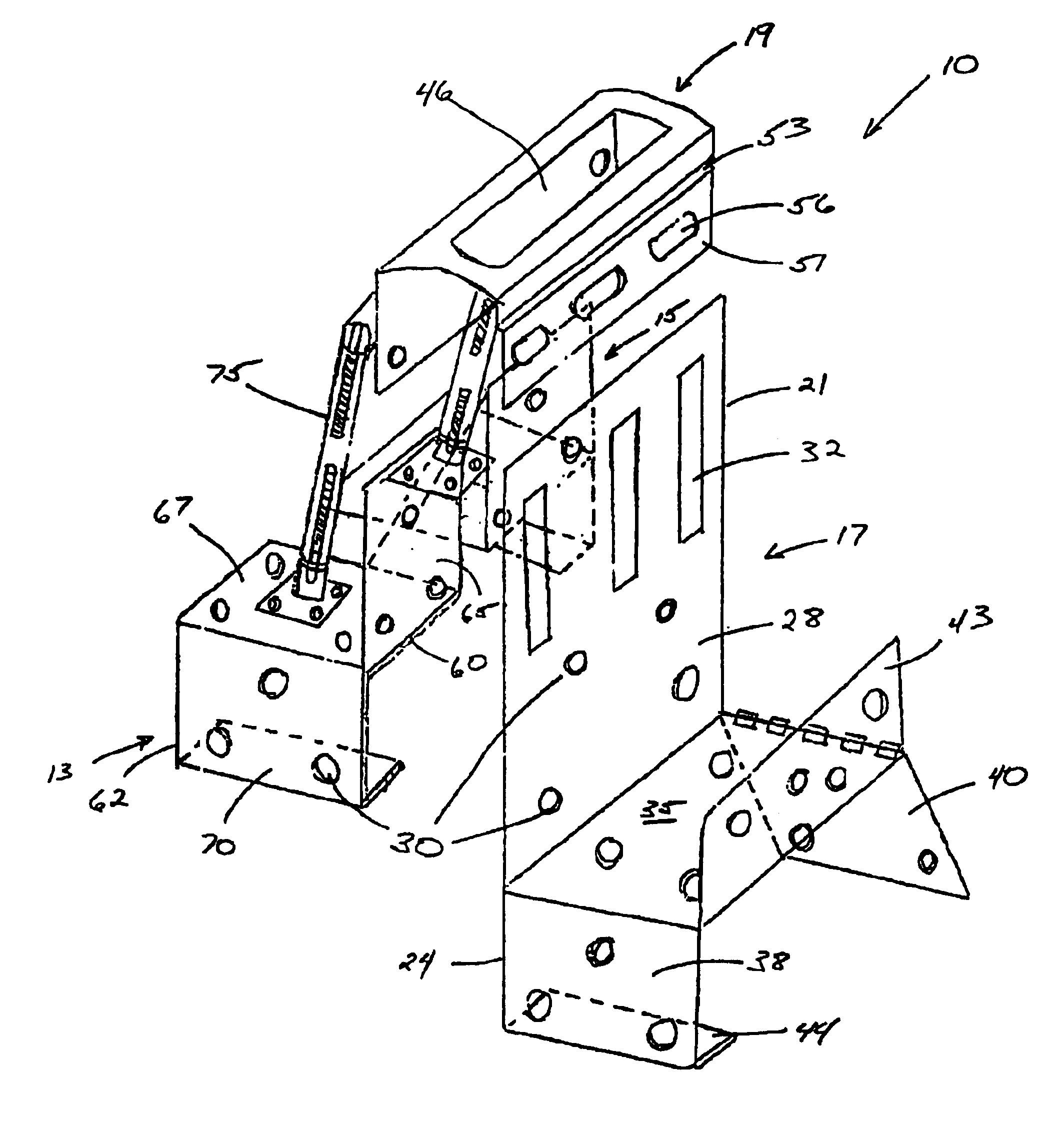
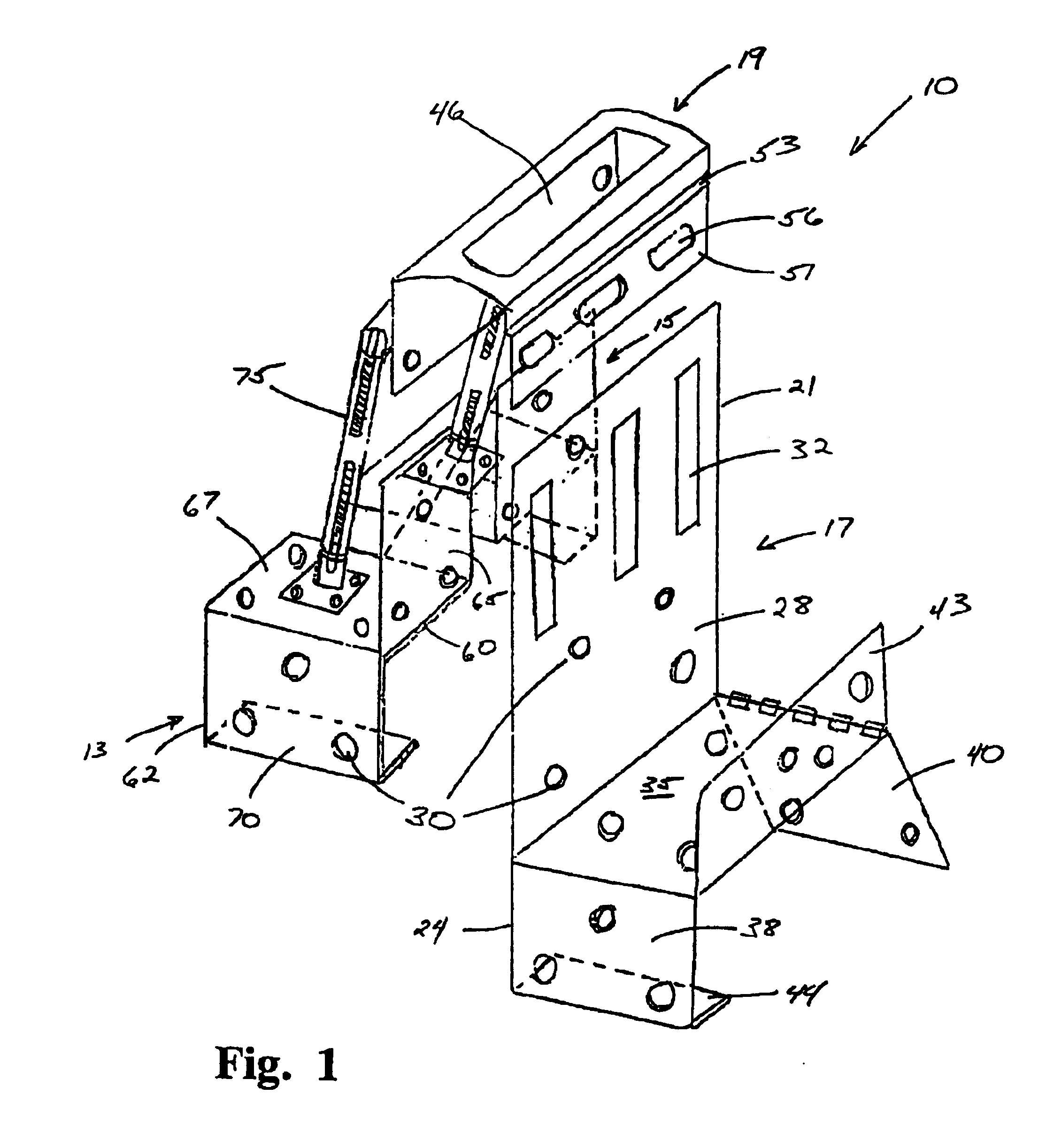
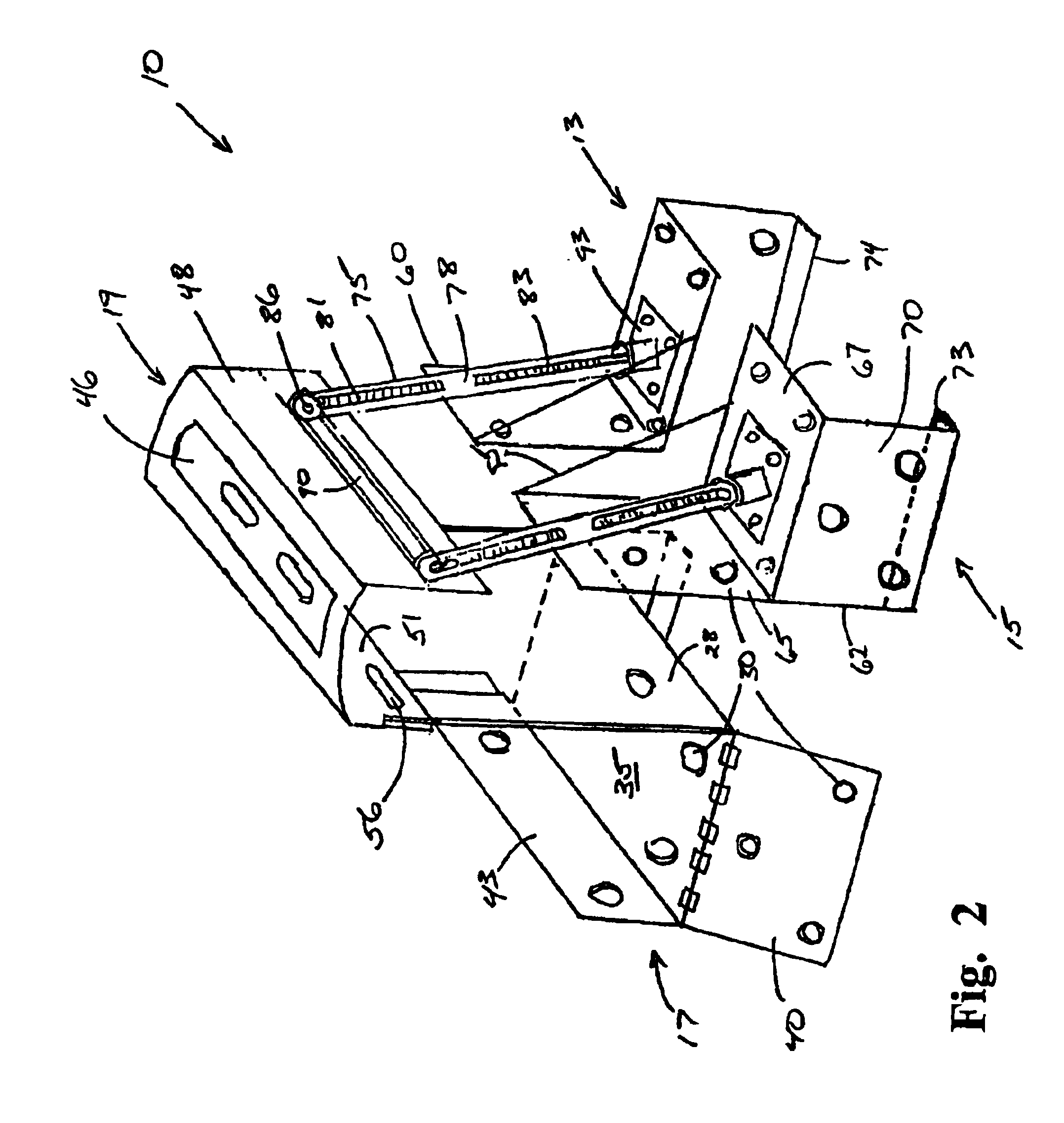
[0030]Referring to FIGS. 1 and 2, a roof tie according to the present invention, indicated generally as 10, is illustrated...


PUM


Abstract

A building roof tie for attaching roof trusses and rafters to wood top plates in building structures, said roof tie having a sheet metal body with risers and a bridge for overlapping a rafter and flaps for wrapping on the sides of the top plate. The flaps may be configured to penetrate into the top plate for additional stability. Turnbuckles attached to the bridge provide additional hold-down strength against increased uplift forces. Such turnbuckles may include a hinge and pin assembly that can adjust up and down, forward and backwards. The roof ties are pitched to conform to a variety of framing applications. A plurality of apertures is formed in the roof tie to provide openings for fasteners for connecting the tie to the wood top plate and rafter.

Description

CROSS-REFERENCE TO RELATED APPLICATIONS[0001]Related Application[0002]This application is a continuation-in-part of co-pending and co-owned U.S. patent application Ser. No. 10 / 604,443, entitled “Tornado and Hurricane Roof Tie”, filed with the U.S. Patent and Trademark Office on Jul. 22, 2003 by the inventor herein, which is a continuation-in-part of co-pending and co-owned U.S. patent application Ser. No. 10 / 211,138, entitled “Tornado and Hurricane Roof Tie”, filed with the U.S. Patent and Trademark Office on Aug. 2, 2002 U.S. Pat. No. 6,837,019 by the inventor herein, the specifications of which are included herein by reference.BACKGROUND OF THE INVENTION[0003]1. Field of the Invention[0004]This invention relates generally to building structures with wood roofs, and more particularly to structures exposed to extreme wind conditions, such as Tornadoes and Hurricanes, where building codes dictate that such structures be protected against structural failure to save lives of occupants....

Claims


Application Information

Patent Timeline
Patent Type & Authority Patents(United States)
IPC IPC(8): E04B7/04E04B7/06E04B1/26
CPCE04B7/045E04B7/063E04B1/2604E04B1/2608
Inventor COLLIE, ANTHONY D.
Owner COLLIE ANTHONY D
Why Eureka
Try Eureka