

Excess flow valve with magnet
a flow valve and magnet technology, applied in the direction of valve operating means/releasing devices, functional valve types, transportation and packaging, etc., can solve the problems of excessive pressure drop, inefficient valve structure, non-symmetric structure, etc., to improve the efficiency of valve operation, simplify the structure of excess flow valves, and reduce the number of valve parts
- Summary
- Abstract
- Description
- Claims
- Application Information
AI Technical Summary
Benefits of technology
Problems solved by technology
Method used
Image

Examples
Embodiment Construction
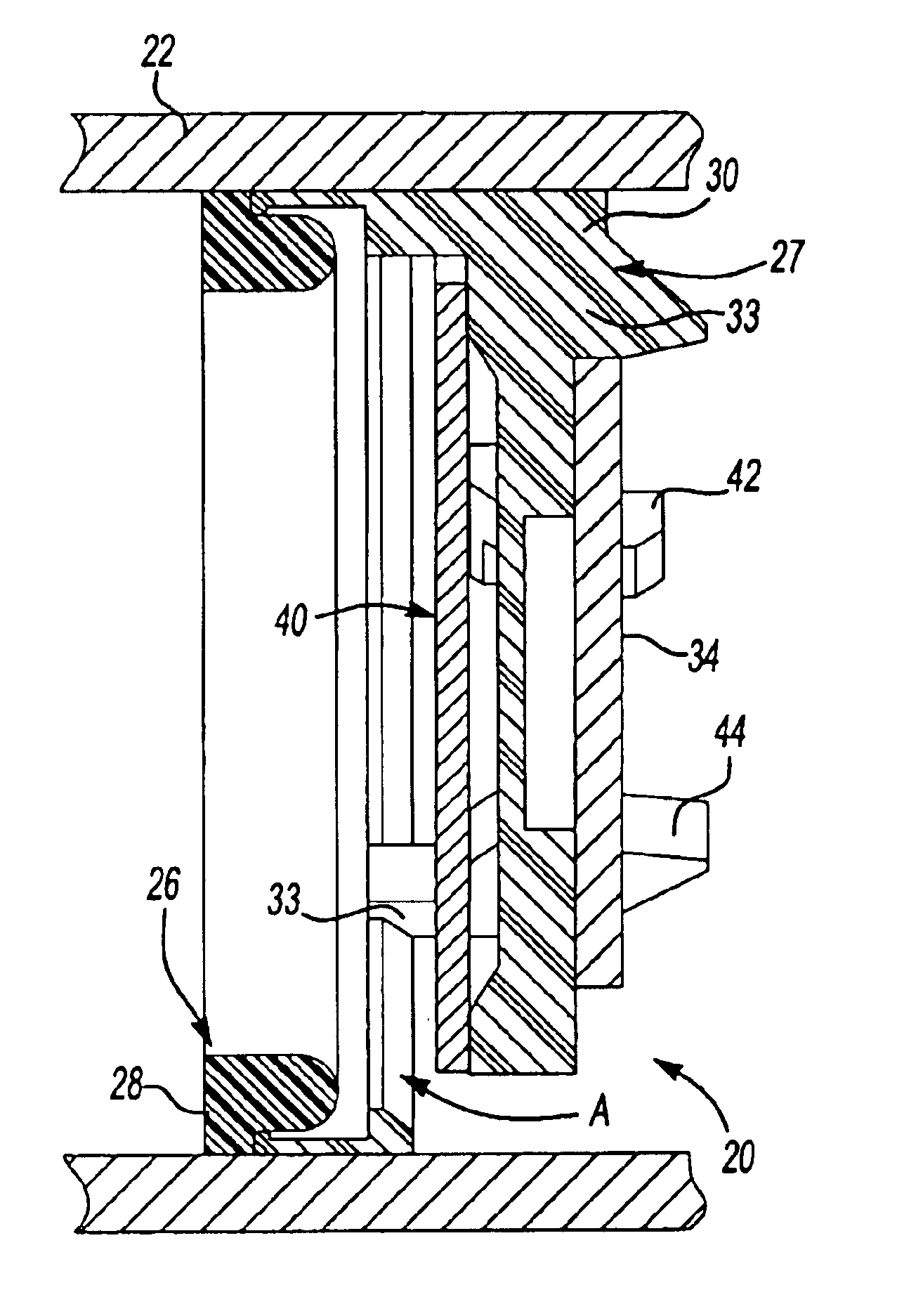
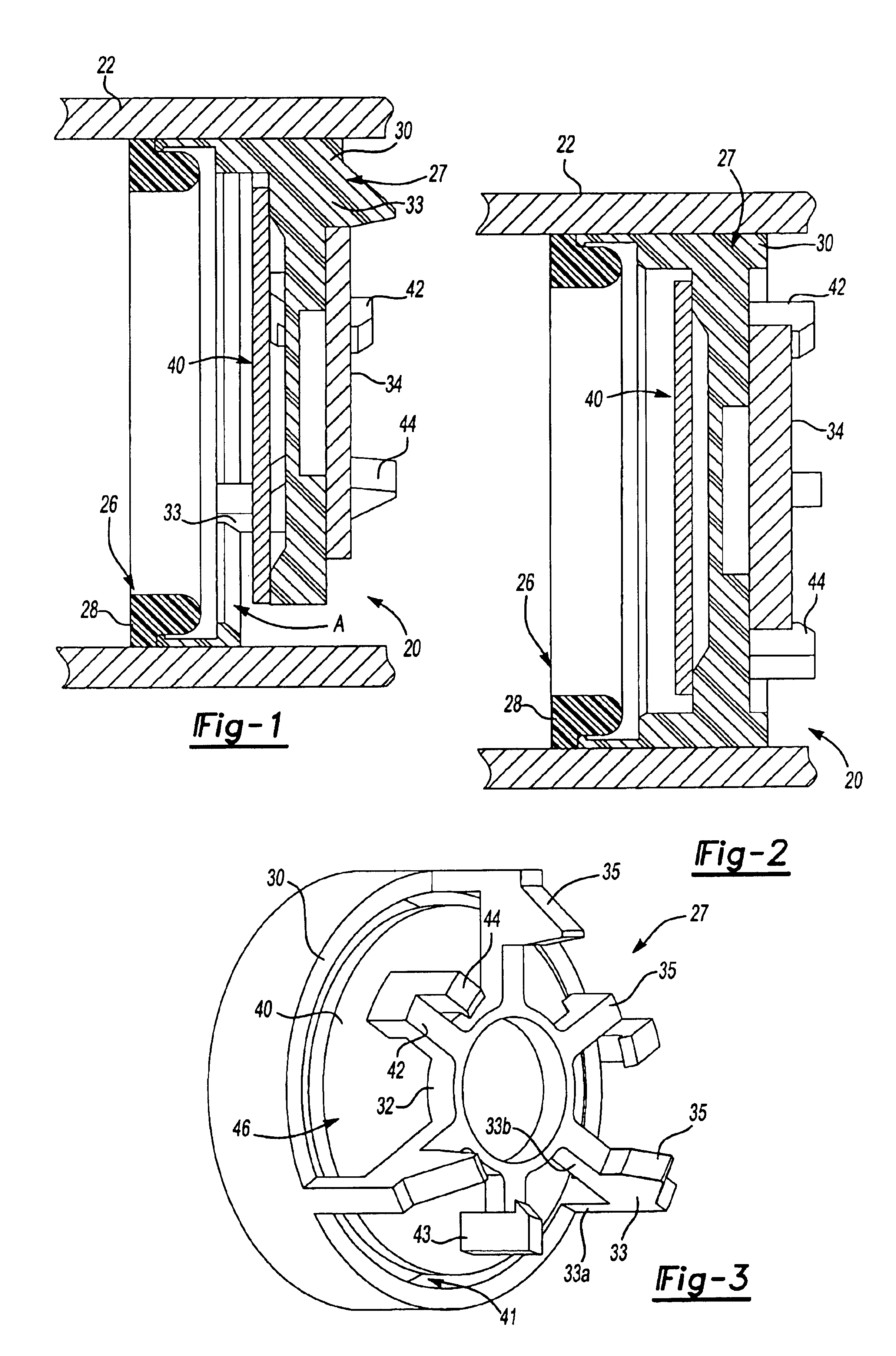
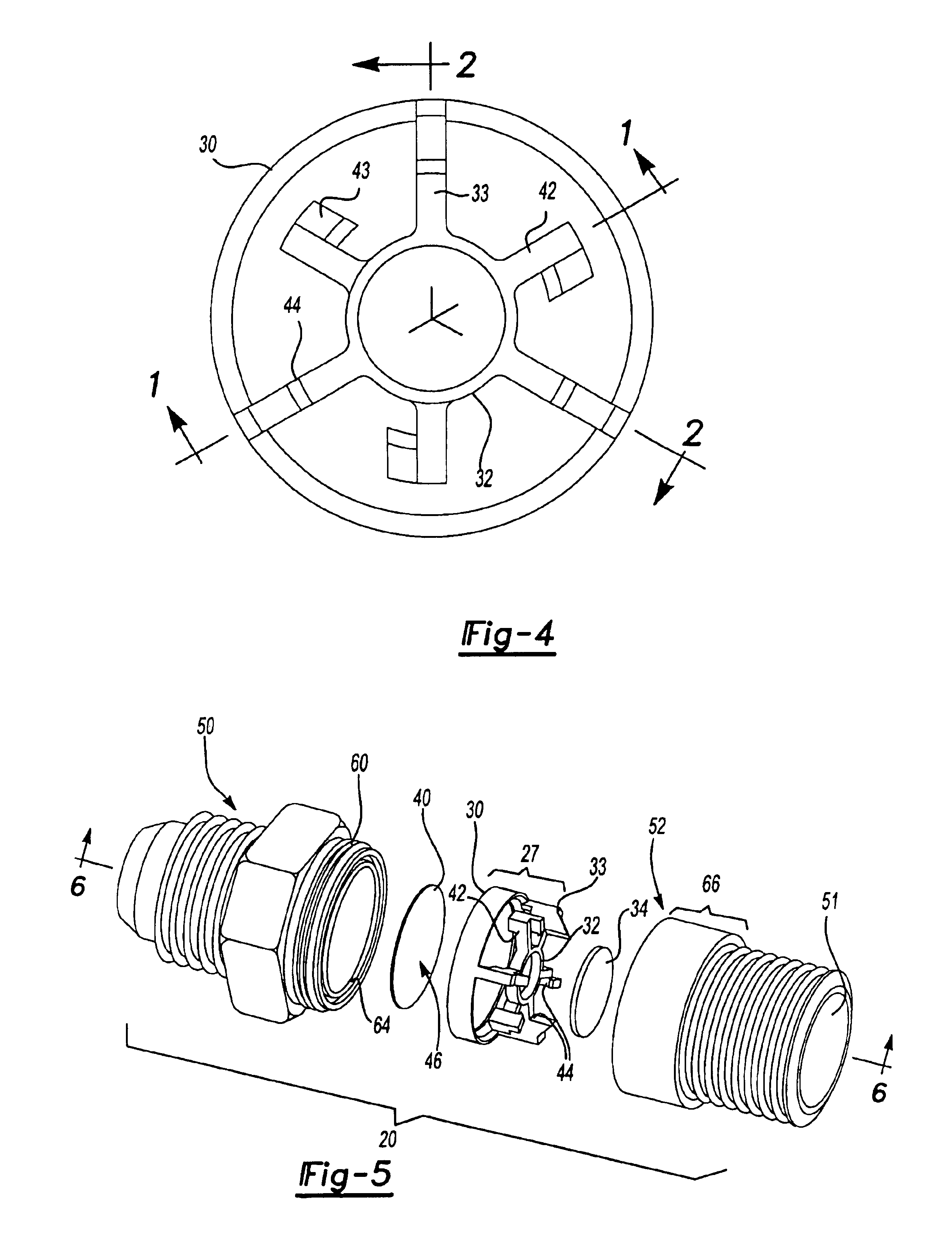
[0018]Referring to FIGS. 1 through 4, an excess flow valve 20 is positioned within a conduit 22. In this embodiment, a valve seat component 26 is provided as a separate element from a valve body 27 in the excess flow valve 20. The valve seat 26 may be made of a resilient material to create a fluid-tight seal. An outer surface 28 of the valve seat 26 engages the inner surface of the conduit 22. An outer peripheral portion 30 of the valve body 27 is ring-shaped and also engages the inner surface of the conduit 22. The valve body 27 in this embodiment also includes an inner hub 32 supported by a first set of arms 33 extending between the outer peripheral portion 30 and the inner hub 32. In one embodiment, the arms have a axial portion 33a and a radial portion 33b. Guide protrusions 35 on the arms 33 form a magnet retention structure to hold a magnet 34, preferably a disk-shaped magnet. Note that the inner hub 32 is an optional structure; if the inner hub 32 is eliminated, the arms 33 m...
PUM
 Abstract
Description
Claims
Application Information