
Aspheric lenses

a technology of ophthalmic lenses and ophthalmic lenses, applied in the field of ophthalmic lenses, can solve the problems of ophthalmic lenses suffering from a number of shortcomings, significantly degrading their performance, and not providing the best focus at the target object distance, etc., and achieve the effect of improving the depth of field

Active Publication Date: 2005-08-02
ALCON INC
View PDF15 Cites 141 Cited by
  • Summary
  • Abstract
  • Description
  • Claims
  • Application Information

AI Technical Summary

Benefits of technology

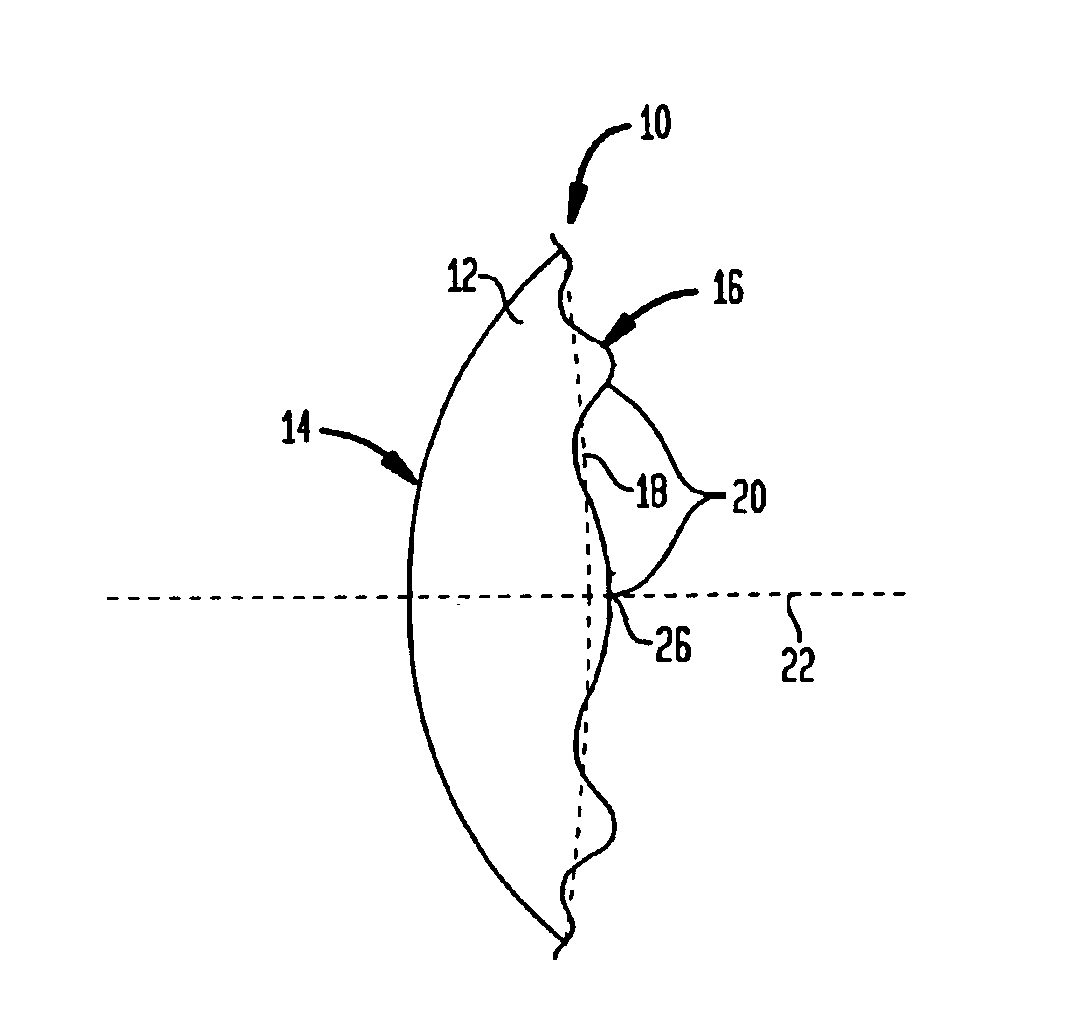
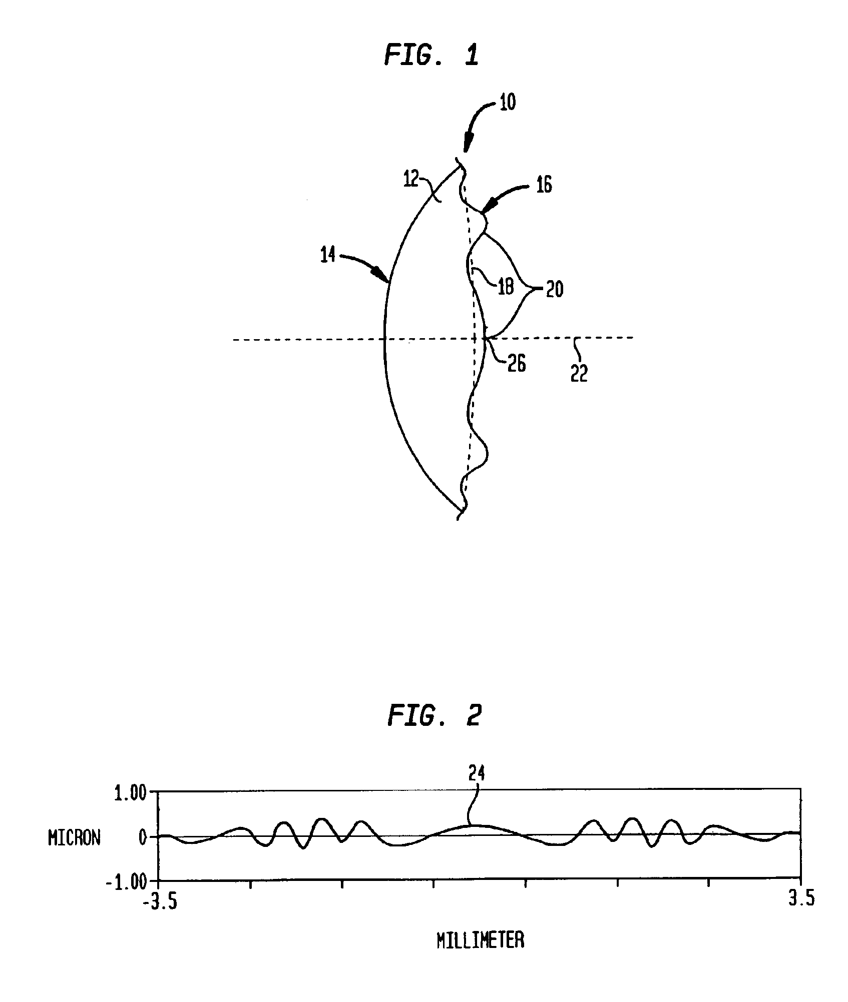
[0005]The present invention provides monofocal ophthalmic lenses that exhibit extended depth of field while providing sufficient contrast for resolution of an image over a selected range of defocus distances. Methods of correcting refractive errors or otherwise enhancing vision over a range of such distances are disclosed, as well as methods of manufacturing the lenses of the present invention. The extended depth of field is achieved by introducing a minor modulation to the base curve of one or more lens elements such that the eye resolves a single image over a range of distances greater than the focal region of a conventional lens, with a modest level of contrast reduction.
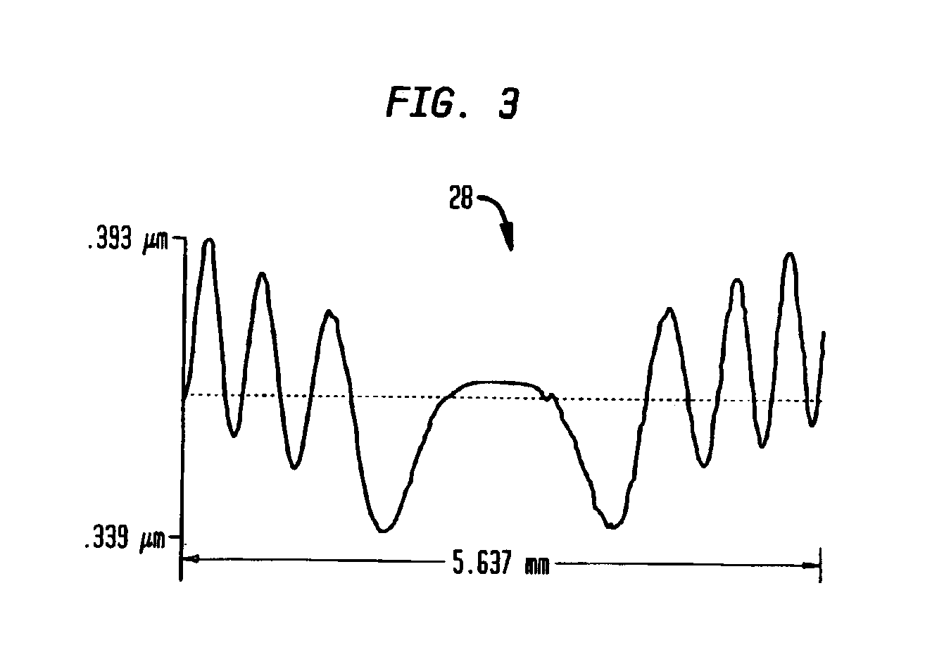
[0007]More particularly, in one aspect, the invention provides a monofocal ophthalmic lens for vision correction that includes a lens optic that provides a nominal diopter power. The lens optic is further characterized by at least one refractive surface having a base curvature and a pattern of surface deviations superimposed on the base curvature so as to modulate the profile of the refractive surface in a range of about −0.5 microns to about +0.5 microns about the base curvature. The surface modulations are designed so as to enhance the depth of field of the lens by at least about 40%, and preferably by at least about 50% percent, and more preferably by at least about 60%, relative to a lens having the same lens optic and the same refractive surface, but without the surface modulation.
[0016]In other aspects, the invention provides methods for forming a lens according to the teachings of the invention. For example, in one such method, in an initial step, a circularly symmetric base profile is selected for at least one refractive surface of the lens. Subsequently, a pattern of surface deviations from the base profile is defined, and is applied to the base profile so as to define a continuously varying topography for the refractive surface. The pattern of surface deviations is selected to be circularly symmetric and continuously varying across the refractive surface so as to effect enhancement of the depth of field of the lens relative to a similar lens that is devoid of the surface deviations.

Problems solved by technology

In many cases, however, the implanted lens may not provide the best focus at the targeted object distance.
Such errors can be caused, for example, by inherent variability associated with calculation methods utilized to choose an IOL's refractive power, inaccuracies in preoperative biometry data, or variations in the IOL's axial placement, tilt or decentration.
Such conventional ophthalmic lenses suffer from a number of shortcomings.
For example, errors in axial placement of conventional monofocal lenses can significantly degrade their performance.

Method used


Image

  • Aspheric lenses
  • Aspheric lenses
  • Aspheric lenses

Examples


example i

[0071]One exemplary method for modeling a refractive lens of the invention having surface deviations from a base profile in which a spline fitting procedure is employed is described below. With reference to FIG. 10, a solid curve 42 represents a base profile of such a refractive surface, which is selected in this example to be spherical. The z-axis is selected to be the optical axis of the lens such as the base profile is symmetric about the z-axis. Hence, only the upper portion of the surface, i.e., positive y direction, is considered with the understanding that the variations in the negative y directions mirror those in the positive y direction.

[0072]A plurality of exemplary off-axis locations A, B, C, D, E, F, G, H, and I each having selected z-axis coordinate and offset from the base profile, are chosen. An initial value of slope is assigned to each of these locations. A spline fitting procedure is employed to form an initial surface, e.g., dashed surface 44, that passes through...


PUM


Abstract

The present invention provides monofocal ophthalmic lenses that exhibit extended depth of field while providing sufficient contrast for resolution of an image over a selected range of defocus distances. In some embodiments, a lens of the invention can include a refractive surface having controlled surface modulations relative to a base profile. The surface modulations are designed to extend a depth of field of the lens such that a single image can be resolved, albeit with somewhat less contrast, over a range of distances greater than the focal region of a conventional lens. The ophthalmic lenses of the invention can be employed in various vision correction applications, including, but not limited to, intraocular lenses, contact lenses, instrastromal implants and other refractive devices.

Description

BACKGROUND OF THE INVENTION[0001]The present invention relates generally to ophthalmic lenses, and more particularly to ophthalmic lenses that provide an enhanced depth of field.[0002]A variety of ophthalmic lenses are employed for correcting visual disorders, such as, cataract, myopia, hyperopia or astigmatism. For example, an intra-ocular lens (IOL) can be implanted in a patient's eye during cataract surgery to compensate for the lost optical power of the removed lens. In many cases, however, the implanted lens may not provide the best focus at the targeted object distance. Some studies have reported that refractive errors as large as 0.5 Diopters can occur in about fifty percent of patients who receive IOLs. Such errors can be caused, for example, by inherent variability associated with calculation methods utilized to choose an IOL's refractive power, inaccuracies in preoperative biometry data, or variations in the IOL's axial placement, tilt or decentration.[0003]A variety of op...

Claims


Application Information

Patent Timeline
IPC IPC(8): A61F2/16
CPCA61F2/1613
Inventor SIMPSON, MICHAEL J.CARSON, DANIEL R.
Owner ALCON INC
Learn More