
Vacuum pump

a vacuum pump and pump body technology, applied in the direction of rotary piston engines, flanged connections, couplings, etc., can solve the problem of relatively low power consumption of vacuum pumps, and achieve the effect of high reliability

Inactive Publication Date: 2005-08-02
HANON SYST EFP DEUT GMBH
View PDF38 Cites 24 Cited by
  • Summary
  • Abstract
  • Description
  • Claims
  • Application Information

AI Technical Summary

Benefits of technology

The invention is a vacuum pump that does not have the disadvantages of previous designs. It is made of plastic and can be produced cost-effectively using injection molding. The rotor is lightweight and compact, which reduces the space needed for the pump. The power consumption of the vacuum pump is low because of the low inertia of the rotor. The rotor can have one or more cavities, which further reduces its weight. The wall thickness of the rotor is continuous, without any discontinuities. The rotor can have at least one closed wall running transversely or essentially transversely to the central longitudinal axis of the rotor. The drive element working together with the rotor can damp torque spikes and prevent breakage of the motor. The rotor can be driven by the internal combustion engine of a motor vehicle or a motor, such as an electric motor. The vacuum pump can be used in a motor vehicle, for example in connection with a brake booster system. The rotor can be optionally driven by the internal combustion engine or the motor.

Problems solved by technology

The power consumption of the vacuum pump is relatively low due to the low inertia of the rotor.

Method used


Image

  • Vacuum pump
  • Vacuum pump
  • Vacuum pump

Examples


Embodiment Construction

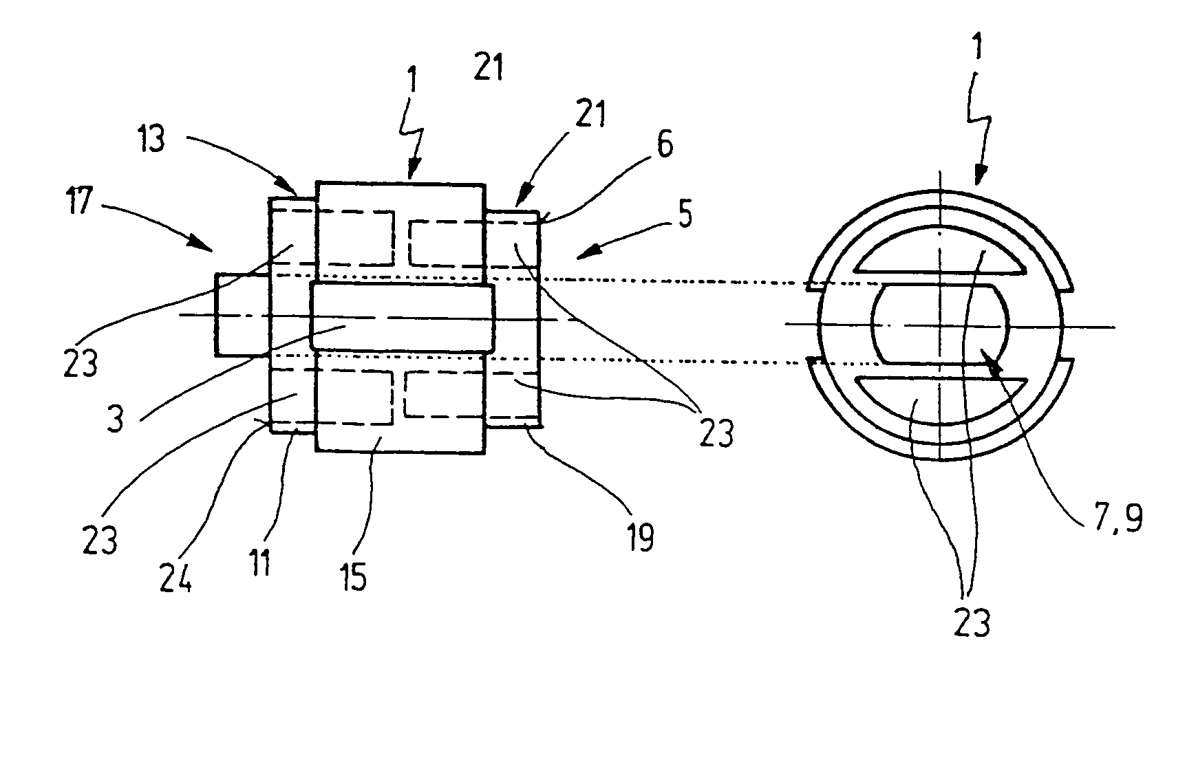
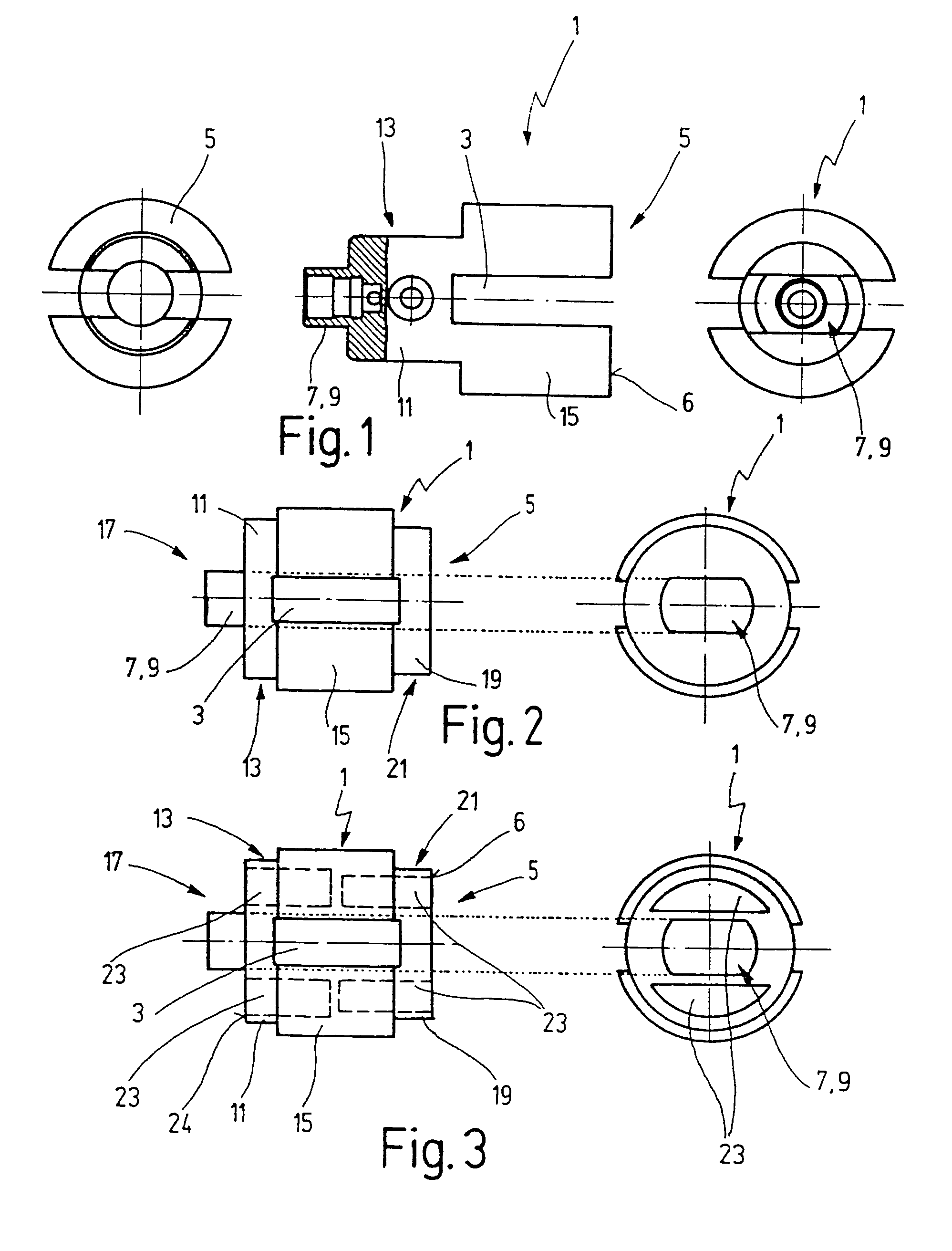
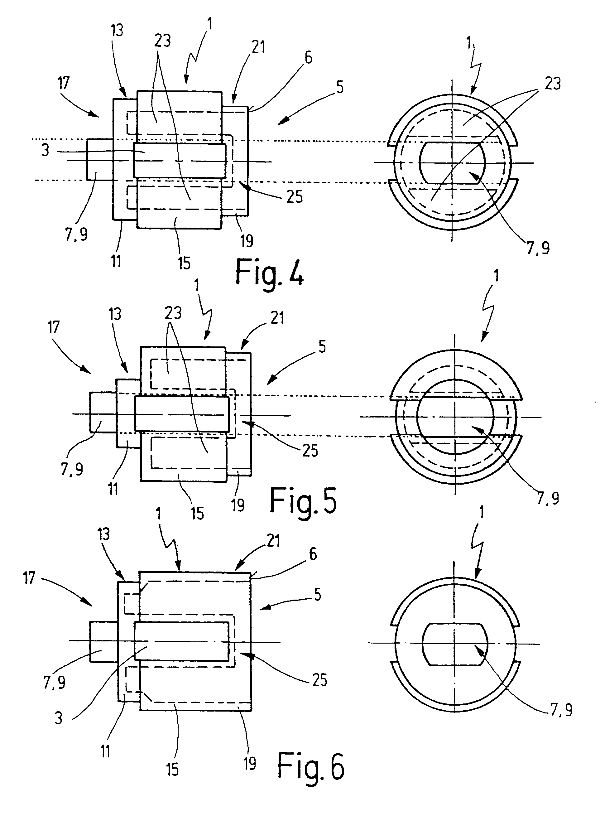
[0033]It is common to each of the exemplary embodiments of the rotor for a vacuum pump described in the following that it is formed as one piece and consists of plastic. The rotor can be produced in an advantageous manner in the injection-molding process and has only a light weight.

[0034]FIG. 1 shows three images of a first exemplary embodiment of the rotor 1 of a vacuum pump not represented, said rotor being provided with a slot 3 passing through. The slot 3 serves to accommodate a blade not represented which can be displaced within the slot 3 in the direction of the diameter. In the case of this exemplary embodiment the slot 3 is introduced into a frontal face 6 from the frontal side 5 turned away from the drive of the rotor 1, and therefore is formed open at the edge. A drive shaft which can be energized with a torque usually serves as drive. The outer face of the rotor 1 is formed cylindrically.

[0035]A first longitudinal section 7 of the rotor formed as the double surface 9 to w...


PUM


Abstract

A vacuum pump, in particular for brake booster systems in motor vehicles, with a drivable rotor via which a blade in a housing can be set in rotation is proposed. The vacuum pump is distinguished by the fact that the rotor consists of plastic and is formed as one piece.

Description

[0001]The present Application is the National Phase of PCT / EP99 / 07111, filed Sep. 24, 1999, claiming priority to German Patent App. No. 29823809.8, filed Sep. 30, 1998.[0002]The invention relates to a vacuum pump, in particular for brake booster systems in motor vehicles, according to the preamble of claim 1.BACKGROUND OF THE INVENTION[0003]Vacuum pumps of the type addressed here are known. They have a rotor consisting of metal, usually sintered metal, which can be set in rotation by a drive shaft. The rotor disposed in a housing is in engagement with a blade which slides along a contour ring. The rotor consists of several individual parts which are removably connected to one another. It has been shown that the rotor has great inertia due to its weight, whereby the power consumption of the vacuum pump is undesirably high. The rotor furthermore has a massive and expensive structure.SUMMARY OF THE INVENTION[0004]It is thus the objective of the invention to provide a vacuum pump of the...

Claims


Application Information

Patent Timeline
Patent Type & Authority Patents(United States)
IPC IPC(8): F01C21/00F01C21/08F04C18/34F04C29/00F04C18/344F04C25/02
CPCF01C21/08F04C18/3442F04C29/005F04C29/0071Y10T403/68Y10T403/7003Y10T403/64F16B2200/50
Inventor OTTO, DIETER
Owner HANON SYST EFP DEUT GMBH
Learn More