Exercise treadmill

Inactive Publication Date: 2005-08-02
BRUNSWICK CORPORATION
View PDF50 Cites 99 Cited by
  • Summary
  • Abstract
  • Description
  • Claims
  • Application Information

AI Technical Summary

Benefits of technology

[0024]The belt pulley construction can be, alternatively, straight cylindrical, convex, or a cylindrical center section and conical ends (cambered). The belt pulleys also have a relatively large diameter, preferably approximately nine inches. The pulleys are of a molded plastic construction and a drive sprocket portion can be molded as part of the pulley. Possible plastic materials from which the pulleys can be molded include glass-filled polypropylene, polystyrene, polycarbonate, polyurethane and polyester. In some embodiments, bearing seat assemblies can be molded-in to the pulley when it is originally manufactured, thereby eliminating the need for inserting and fastening bearing seats into molded pulleys.
[0025]The use of large diameter pulleys is facilitated through the use of a plastic construction, rather than a steel construction. The large diameter of the pulleys permits the use of thicker belts which can be made to be more shock-absorbing than currently used belts. User comfort is therefore further enhanced. The larger pulleys also reduce the belt tension required for satisfactory belt drive.
[0026]A belt position sensor mechanism provides for positive lateral tracking of the belt. As a result, the belt is prevented from laterally sliding too far to one side of the pulley so that it contacts a frame or other portions of the structure, resulting in a reduction of wear or damage to the belt. This arrangement is also less sensitive to improper adjustment and side loading.
[0027]The sensor mechanism includes an arm which is spring biased to one edge of the lower surface of the belt, preferably near the front belt pulley. As the belt moves to one side or the other on the front pulley, the arm moves in the same direction as the lateral movement of the belt. In one of two designs, a Hall effect sensor connected to the arm electrically measures the lateral movement of the belt, and the electrical signals are transmitted to a microprocessor. If correction of the belt position is required, the microprocessor will activate a front pulley pivoting mechanism to pivot one end of the front pulley in a longitudinal direction, either towards the front or towards the rear of the

Problems solved by technology

Because the belt engages the deck surface, friction between the belt and the deck arises and the belt is therefore subject to wear.
Further, most of the decks are rigid resulting in high impact loads as the user's feet contact the belt and the deck.
This is often perceived by users as being uncomfortable and further can result in unnecessary damage to joints as compared to running on a softer surface.
Unfortunately, these surfaces for the most part have not provided the desired level of comfort because the running surface tends to retain its inherent stiffness.
Attempts to solve this problem by using a thicker belt to provide a more shock absorbent running surface have not been successful for the reasons given in U.S. Pat. No. 4,614,337.
Specifically, the thickness of the belt has to be limited in order to limit the belt drive power to reasonable levels.
Pulleys used in current exercise treadmills typically are made of steel or aluminum and as such are relatively expensive to make and are relatively heavy.
Therefore, because of tooling, manufacturing and material costs, the diameter of the pulleys are normally no larger than three to four inches.
Additionally, the diameter of the pulley directly affects the power required to rotate the pulley as does the thickness of the belt.
A further disadvantage of smaller pulleys results from the fact that the reduced surface area of the pulley contacting the belt requires increased te

Method used


Image

  • Exercise treadmill
  • Exercise treadmill
  • Exercise treadmill

Examples


Embodiment Construction

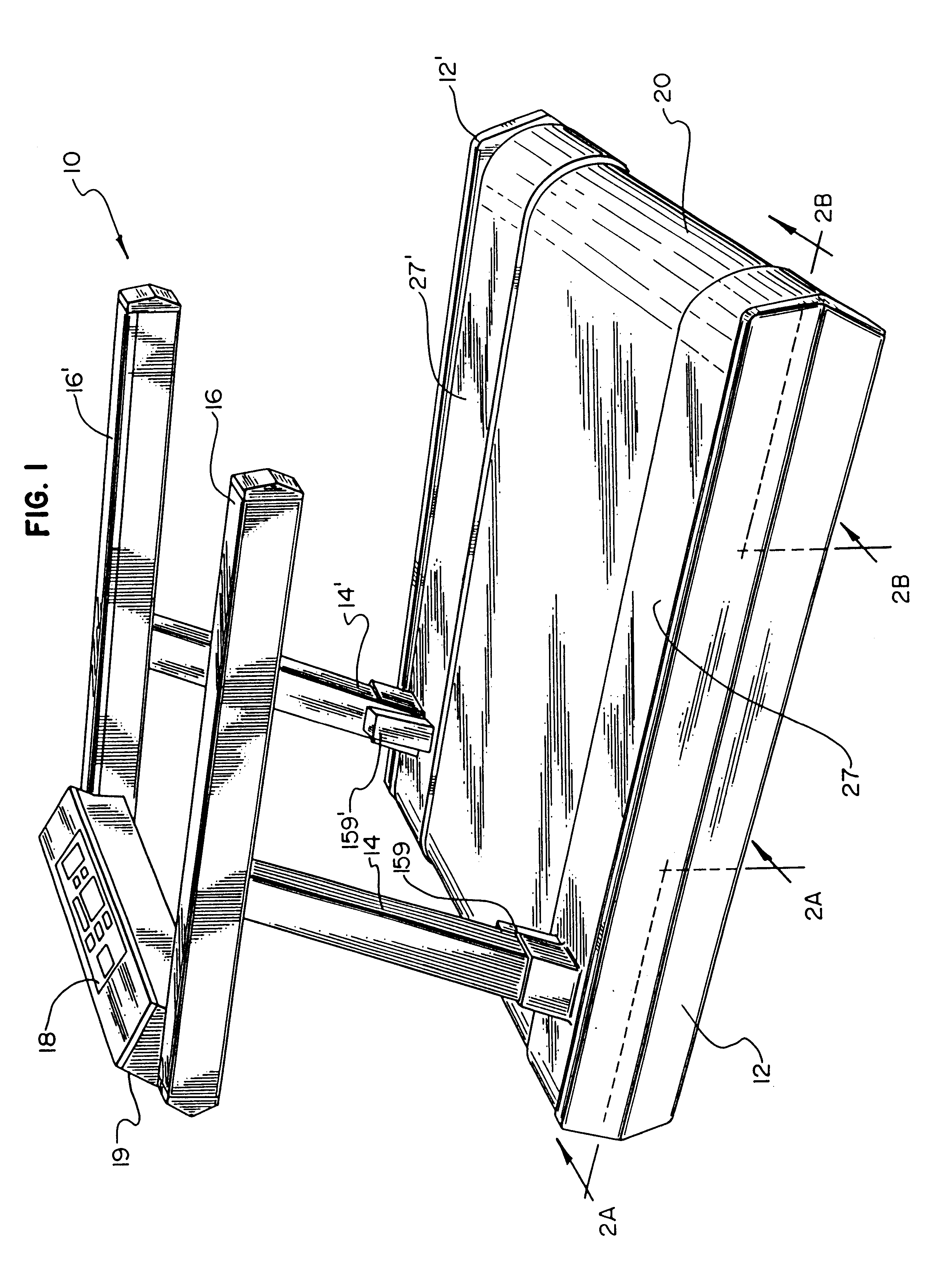
[0058]FIG. 1 provides a perspective view of an assembled exercise treadmill 10. The treadmill 10 has a lower frame portions 12 and 12′ housing the internal mechanical components of the treadmill 10, as discussed below. Projecting upwardly from frame 12 and 12′ are a pair of railing posts 14 and 14′. As illustrated in FIG. 1, railing posts 14 and 14′ are slightly tilted from perpendicular relative to lower frame 12 and 12′, primarily for aesthetic purposes. Secured to the tops of railing posts 14 and 14′ are a pair of side rails 16 and 16′. respectively. Side rails 16 and 16′ provide the treadmill user with a means of support either during the entire exercise period or for an initial period until the user has assimilated himself to the speed of the treadmill. Extending between and attached to the side rails 16 and 16′ is a front rail 17 and a control panel 18 mounted on crossmember 19. Front rail 17 provides vet another means of support for the treadmill user. Control panel 18 includ...


PUM


Abstract

To improve tracking, an exercise treadmill is provided with a frame including molded plastic pulleys, having an integral gear belt sprocket, an endless belt extending around the pulleys and a motor operatively connected to the rear pulley to drive the belt. The pulleys are molded out of plastic and have a diameter of approximately nine inches. A mold and method for producing large diameter treadmill pulleys having an integrally molded sprocket are also disclosed. A deck underneath the running surface of the belt is supported by resilient members. A positive lateral belt tracking mechanism is used to correct the lateral position of the belt. A belt position sensor mechanism is used in combination with a front pulley pivoting mechanism to maintain the belt in the desired lateral position on the pulleys. The exercise treadmill also includes a lift mechanism with an internally threaded sleeve engaged to vertically aligned nonrotating screws. A user display of foot impact force on the belt is also provided.

Description

[0001]This application is a continuation of U.S. Ser. No. 09 / 073,400, filed May 7, 1998, now U.S. Pat. No. 6,095,951 which is a continuation of U.S. Ser. No. 08 / 574,366, filed Dec. 18, 1995, now U.S. Pat. No. 5,752,897, which is a division of application number 08 / 254,030, filed Jun. 3, 1994, now U.S. Pat. No. 5,484,362, which is a continuation-in-part of U.S. Ser. No. 07 / 686,906, filed Apr. 17, 1991, now U.S. Pat. No. 5,382,207, which is a continuation-in-part of U.S. Ser. No. 07 / 452,885, filed Dec. 19, 1989, now abandoned, which is a continuation-in-part of U.S. Ser. No. 07 / 368,450, filed Jun. 19, 1989, now abandoned.FIELD OF THE INVENTION[0002]The invention generally relates to exercise equipment and in particular to exercise treadmills.BACKGROUND OF THE INVENTION[0003]Exercise treadmills are widely used for various purposes. Exercise treadmills are, for example, used for performing walking or running aerobic-type exercise while the user remains in a relatively stationary positio...

Claims


Application Information

Patent Timeline
IPC IPC(8): A63B22/00A63B22/02A63B24/00
CPCA63B22/0023A63B22/02A63B2022/0214A63B2022/025A63B2220/17A63B2220/53A63B22/0214A63B22/025
Inventor SKOWRONSKI, RICHARD E.LANTZ, KENNETH F.LEON, TOMAS F.LEON, JOSE A.ALEXANDER, DONALD JAMESKOLOMAYETS, GEORGEADAMS, VINCENT C.SZYMCZAK, EUGENE B.MINNICH, EDWARD W.TOTZKE, WADE K.
Owner BRUNSWICK CORPORATION
Why Eureka
Try Eureka