Battery, battery charger, electrical system and method of charging a battery

Inactive Publication Date: 2005-08-02
MILWAUKEE ELECTRIC TOOL CORP
View PDF14 Cites 61 Cited by
  • Summary
  • Abstract
  • Description
  • Claims
  • Application Information

AI Technical Summary

Benefits of technology

[0014]One independent advantage of the present invention is that the extended terminal of the battery or the charger is connected to the corresponding terminal of the other of the battery or the charger before the other terminal(s) are connected to the other corresponding terminal(s). This “hot plug” gap ensures that the extended terminal end connects to the corresponding terminal before the other terminal ends connect to the other corresponding terminal ends even if the battery is connected to the charger in a canted or angled orientation. This prevents damage to the battery charger and/or to the battery.
[0015]Another independent advantage of the present invention is

Problems solved by technology

One independent problem with existing batteries and existing battery chargers is that, when the battery is connected to the battery charger with the battery charger connected to the power source (i.e., a “hot plug”), if the battery power terminal is connected to the corresponding charger terminal before the battery ground terminal is connected to the corresponding charger terminal, the battery charger and/or the battery may be damaged (i.e., the components of the charging circuit, such as, for example, a microprocessor or microcontroller, may be dama

Method used


Image

  • Battery, battery charger, electrical system and method of charging a battery
  • Battery, battery charger, electrical system and method of charging a battery
  • Battery, battery charger, electrical system and method of charging a battery

Examples


Embodiment Construction

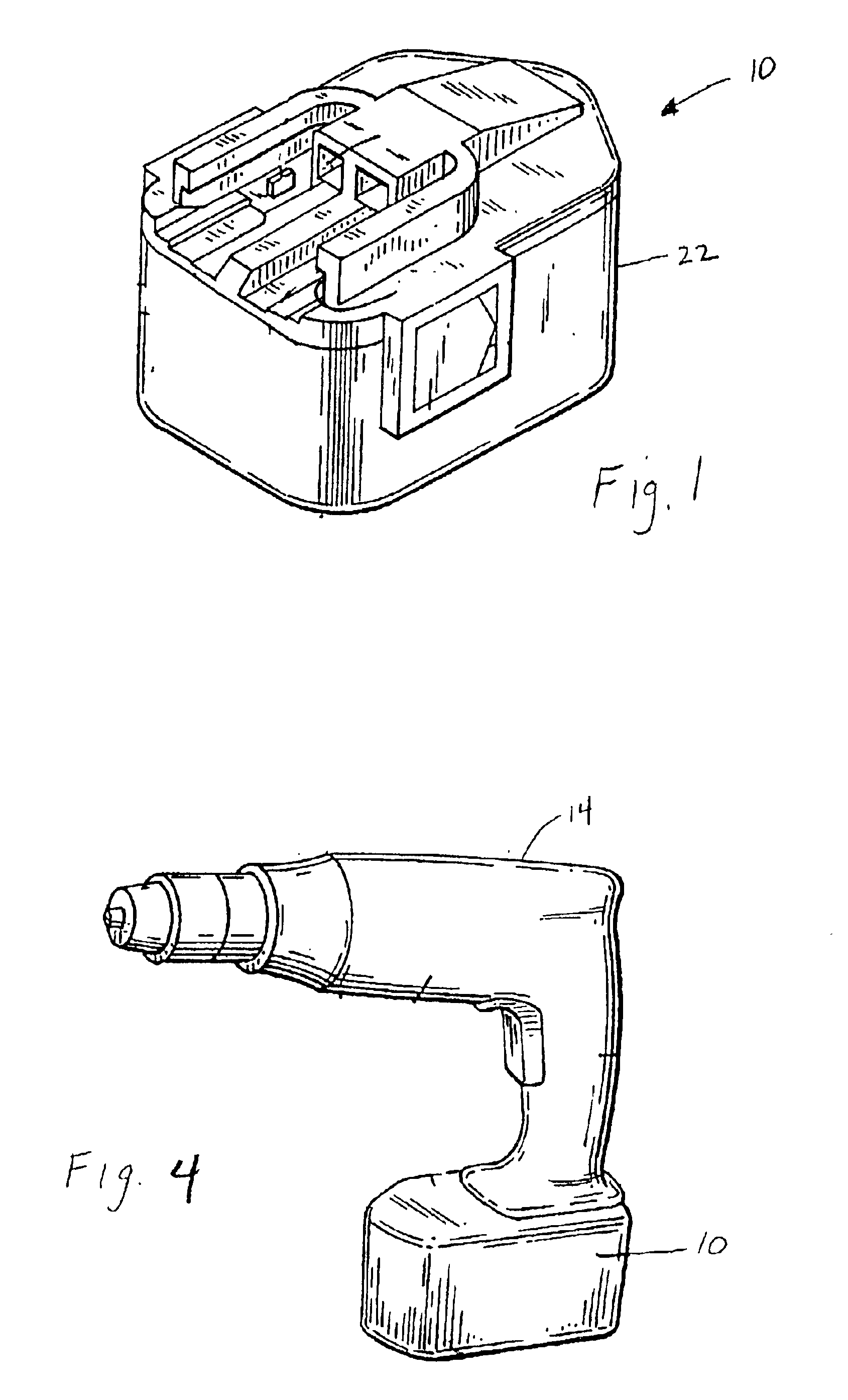
[0032]A battery 10 embodying an aspect of the invention is illustrated in FIG. 1. The battery 10 is connectable to electrical equipment, such as, for example, a cordless power tool 14 (shown in FIG. 4) to selectively power the power tool 14. The battery 10 is removable from the power tool 14 and is preferably rechargeable by a battery charger 18 (shown in FIG. 5).

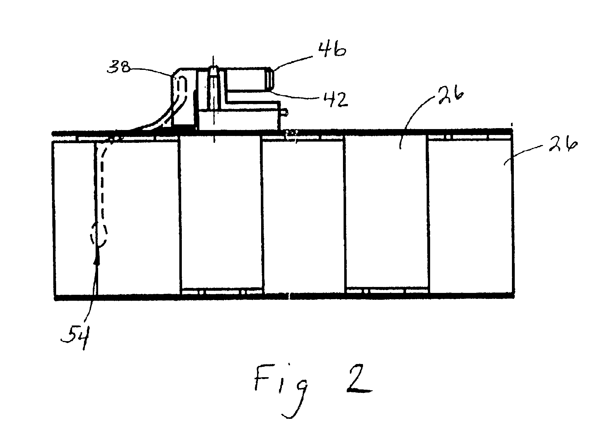
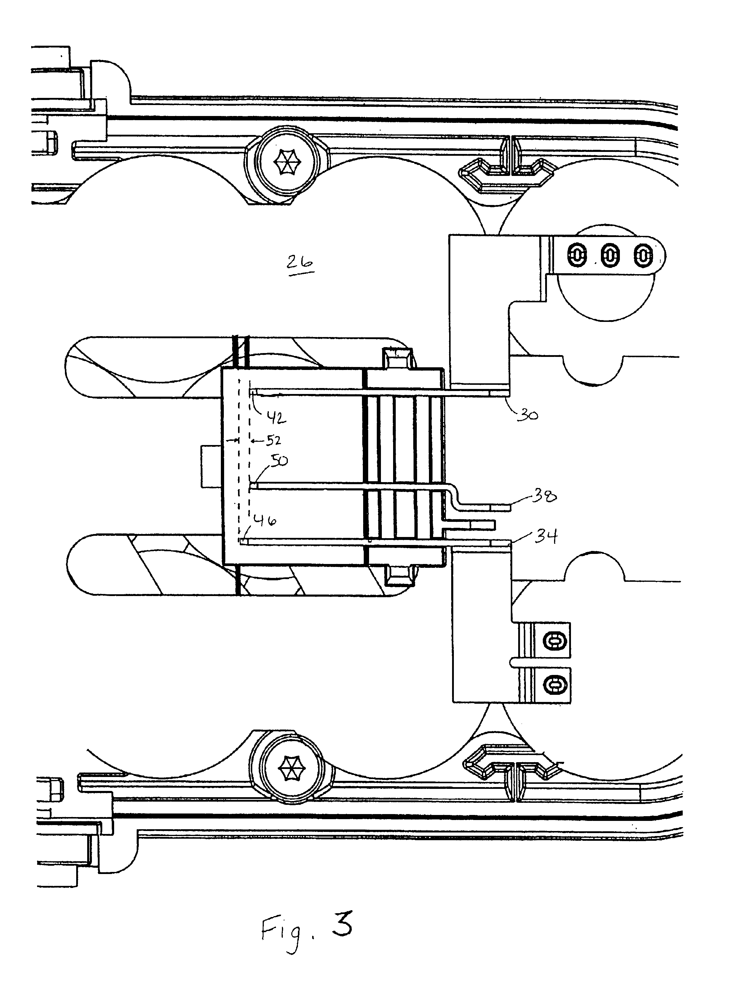
[0033]As shown in FIGS. 1-3, the battery 10 includes a housing 22 and at least one rechargeable battery cell 26 supported by the housing 22. In the illustrated construction, the battery 10 is an 18V battery pack including fifteen approximately 1.2V battery cells 26 connected in series. In other constructions (not shown), the battery 10 may provide another voltage, such as, for example, 12V, 14.4V, 24V, etc., to power the electrical equipment. The battery cell 26 may be any rechargeable battery cell chemistry type, such as, for example, nickel cadmium (NiCd), nickel metal-hydride NiMH) or lithium ion (Li-ion). It should be u...


PUM


Abstract

A battery, a battery charger, an electrical system, and a method of charging a battery. In one aspect, the battery includes a housing, a battery cell supported by the housing, a first terminal electrically connected to the battery cell and having a first terminal end, and a second terminal electrically connected to the battery cell and having a second terminal end, the second terminal end extending forwardly of the first terminal end. In another aspect, the battery charger includes a charger housing, a charging circuit supported by the charger housing and connectable to a power source, a first charger terminal connected to the charging circuit and having a first charger terminal end, the first charger terminal being connectable to the first battery terminal, and a second charger terminal connected to the charging circuit and having a second charger terminal end, the second charger terminal being connectable to the second battery terminal, the second charger terminal end extending forwardly of the first charger terminal end.

Description

FIELD OF THE INVENTION[0001]The present invention relates to batteries and, more particularly, to rechargeable batteries.BACKGROUND OF THE INVENTION[0002]Typically, electrical equipment, such as, cordless power tools, are powered by a rechargeable battery that is periodically charged in a compatible battery charger. To charge the battery, the battery terminals are connected to the charger terminals to connect the battery cell(s) to the charging circuit, and the charging circuit is connected to a power source to selectively supply power to the battery cell to charge the battery cell.SUMMARY OF THE INVENTION[0003]Existing batteries include battery terminals having battery terminal ends which are aligned. Similarly, existing battery chargers include charger terminals having charger terminal ends which are aligned. One independent problem with existing batteries and existing battery chargers is that, when the battery is connected to the battery charger with the battery charger connected...

Claims


Application Information

Patent Timeline
IPC IPC(8): B25F5/00B25F5/02H02J7/00H01M10/30H01M10/34H01M10/40H01M10/44H01M10/46H01M50/213H01M50/247H01M50/296H01M50/59
CPCB25F5/02H01M2/1022H01M2/34H01M2/348H01M10/46H02J7/0042H01M10/44Y02E60/10H01M50/581H01M50/247H01M50/296H01M50/59H01M50/213
Inventor SANTANA, JR., GEORGE L.
Owner MILWAUKEE ELECTRIC TOOL CORP
Why Eureka
Try Eureka