
Electrical resistance monitoring device

a monitoring device and resistance technology, applied in the direction of measurement devices, burglar alarms by opening, instruments, etc., can solve the problems of affecting the safety of people, the possibility of legal action, and the attendant bad publicity, so as to simplify the installation of the device, the effect of convenient and convenient us

Inactive Publication Date: 2005-08-02
NEWSON GALE
View PDF15 Cites 6 Cited by
  • Summary
  • Abstract
  • Description
  • Claims
  • Application Information

AI Technical Summary

Benefits of technology

[0015]The device according to the invention is advantageous primarily in that it provides a continuous indication of the resistance of the conductive element, eg to confirm effective connection of the conductive element to earth. Should the resistance rise, eg because the connection to earth is broken, the user is alerted by a change in the signal emitted by the signalling means. Such a change may be that the signalling means is actuated to produce an audible or visual signal, or alternatively that such a signal is switched off. The device may be compact, self-contained and portable, thereby providing greater convenience of use. The device may also be manufactured at lower cost than conventional earth monitoring systems. The device may also have an intrinsically safe design, enabling it to be used in potentially hazardous environments. In particular, the clamp may be designed in such a way that the risk of emission of energy from it (eg by spark discharge) is minimised. To this end all components of the clamp body may be made conductive and cross-bonded so that no part of the clamp body is electrically isolated and capable of accumulating static charge. The number of components (such as capacitors) which are capable of storing energy may also be kept to a minimum.
[0018]Application of the clamp by means of spring-loaded jaws has the advantage that the clamp may be positioned easily using just one hand, even where the user is wearing protective gloves or other clothing. Other forms of application may, however, be used where appropriate, eg clamping by threaded bolts or the like.
[0021]The signalling means is most preferably a visual signalling means, though other forms of signalling device (eg audible signals, such as a loudspeaker, buzzer etc) may be used. The preferred visual signalling means is a lamp which is illuminated continuously or intermittently so long as the measured resistance has a value less than the predetermined value. Of course, the lamp may alternatively become illuminated only if the resistance is, or becomes, higher than that value. For reasons of compactness, robustness and low cost, the preferred form of lamp is a light-emitting diode (LED).
[0022]It is strongly preferred that the device is provided with its own independent power supply, rather than being connected to a mains supply. This greatly simplifies installation of the device and renders it more portable and versatile. Power for the monitoring unit is thus preferably provided by a battery. The battery is preferably of a type in which it is impossible to discharge all of the energy simultaneously. A particularly preferred form of battery is a lithium manganese battery with a safety non-resettable shut-down mechanism.

Problems solved by technology

Indeed, in any organisation that stores, handles or processes flammable liquids, powders, gases or vapours, there is every likelihood of exposure to the risk of static-caused ignitions within hazardous atmospheres.
Apart from business interruption costs resulting from lost product, these incidents may cause serious injury to people and damage to plant and the environment, as well as the possibility of legal action and the attendant bad publicity for the organisation concerned.
If the clamp is not properly applied, or if the equipment is coated with insulating material, eg paint or an insulating oxide, such connection may not be achieved.
The clamp is then ineffective in discharging any accumulating electrostatic charge and there exists a danger of spark discharge, and the attendant risk of explosion.
They do not provide any monitoring capability to alert a user in the event that the connection to ground is not made, eg due to loose application of the clamp to the equipment or the presence of paint or other insulating covering.
Circuit designs which do monitor the quality of a connection to earth are known, but are generally embodied in complex units which are not portable and hence of limited usefulness.
Such units may also not be sufficiently protected to be located in hazardous areas.

Method used


Image

  • Electrical resistance monitoring device
  • Electrical resistance monitoring device
  • Electrical resistance monitoring device

Examples


Embodiment Construction

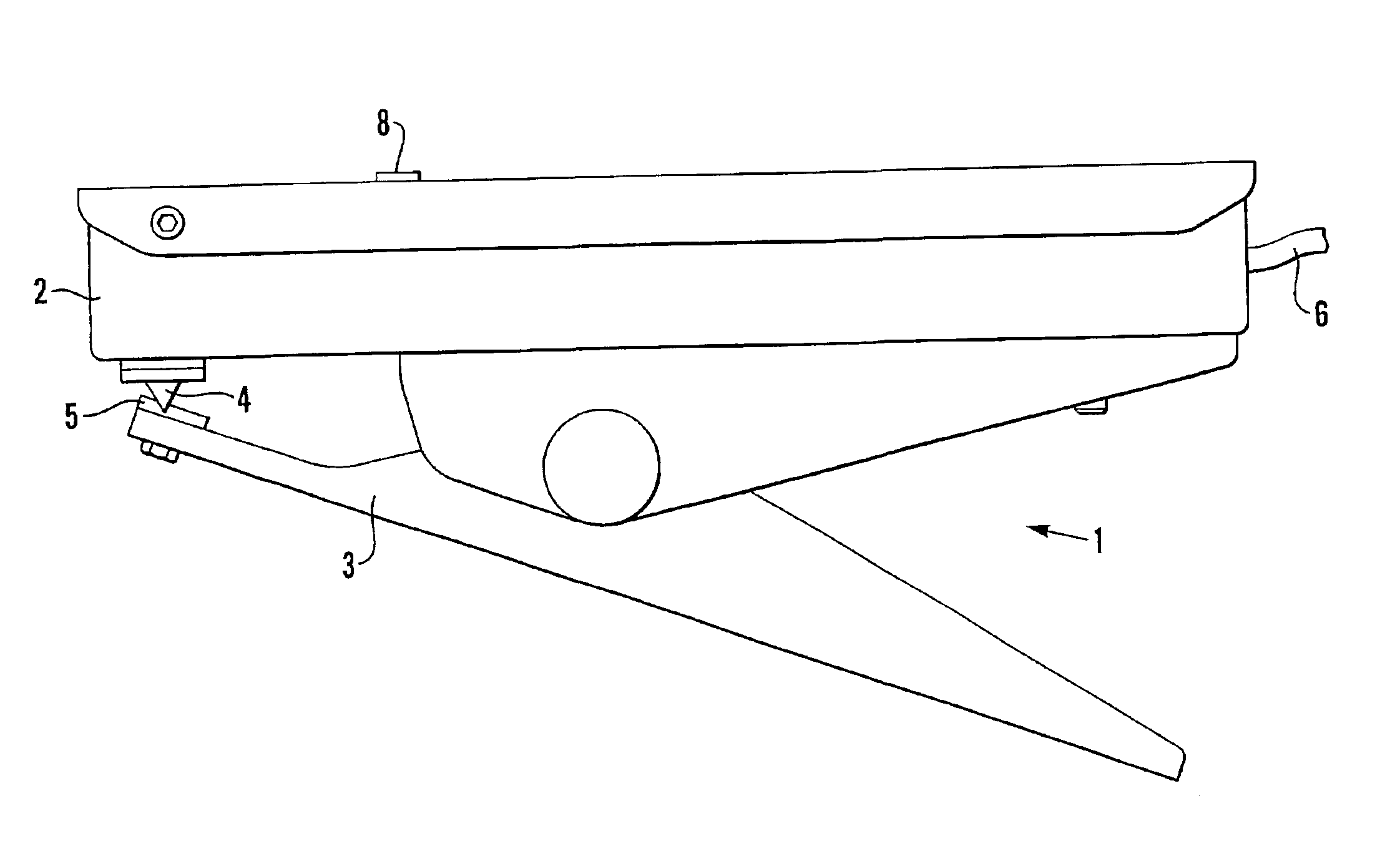
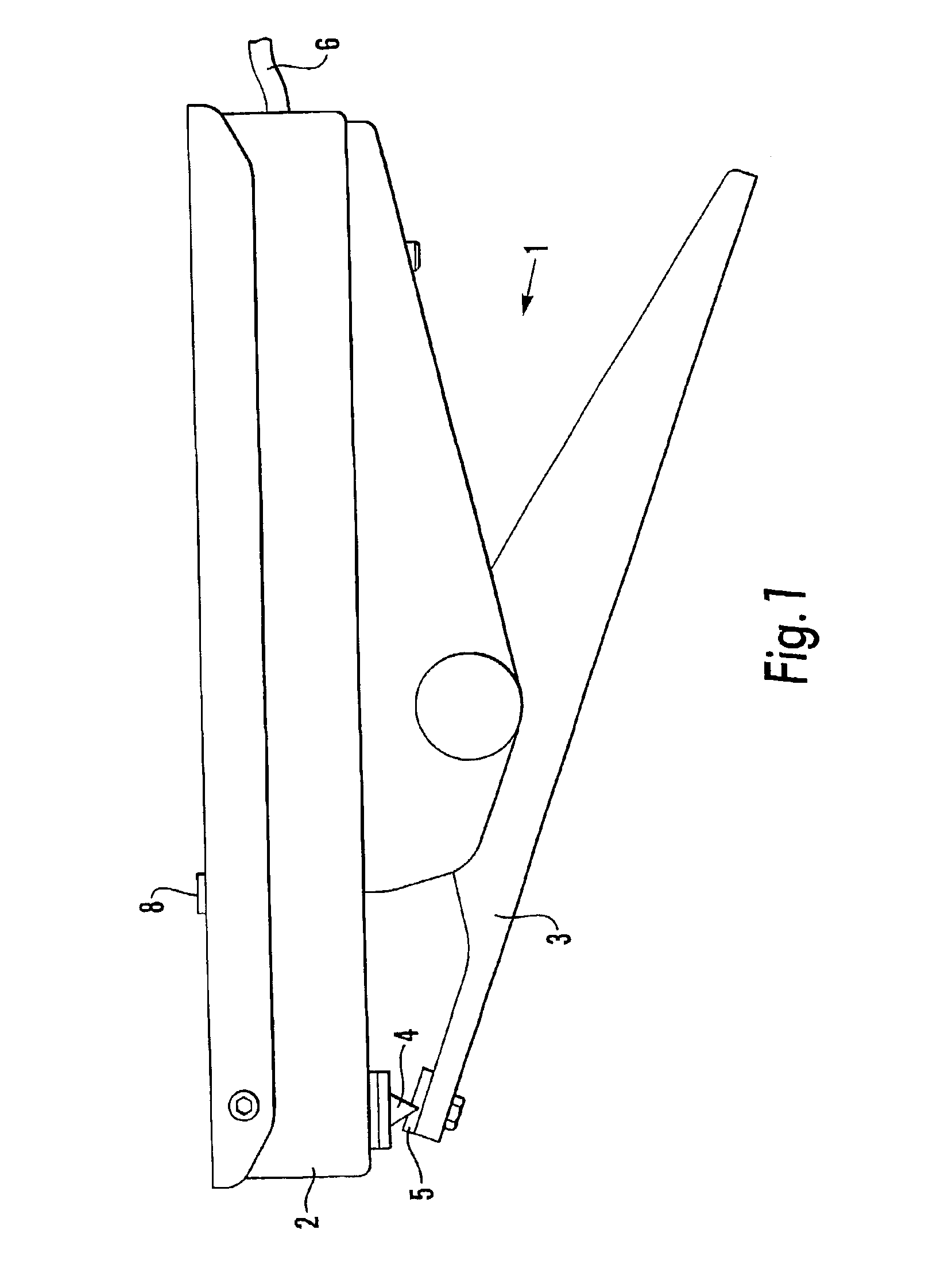
[0030]Referring first to FIG. 1, a first embodiment of the invention comprises a grounding clamp that is generally designated 1. The clamp 1 comprises, in conventional fashion, a pair of spring-loaded jaws 2,3, the tips of which are fitted with juxtaposed mechanical point contacts 4,5 (described more fully below). A two-core earth cable 6 is connected to the clamp 1. The cable 6 may be in the form of flexible spiral cable or may be wound on a spring-loaded self-retracting cable drum.

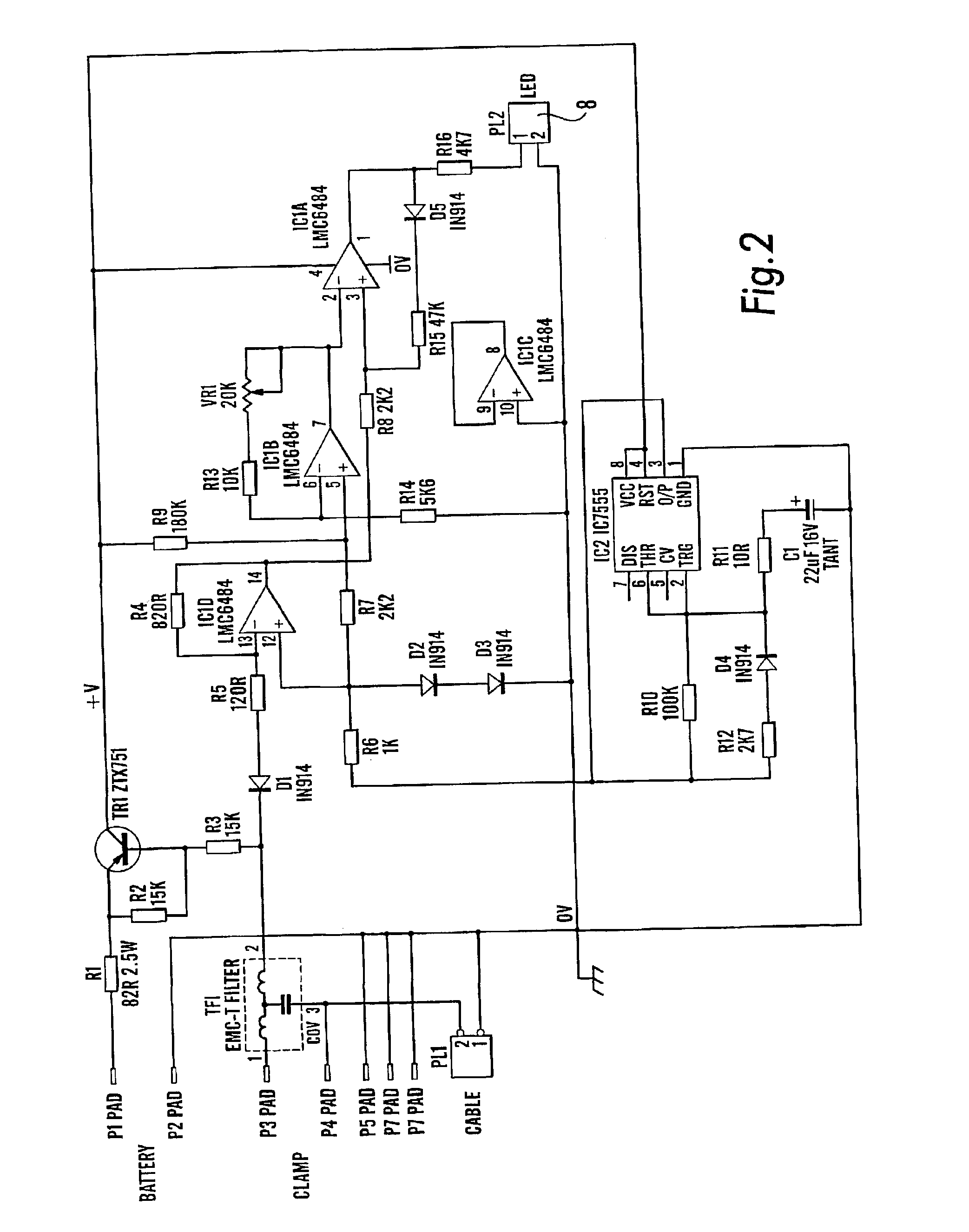
[0031]The resistance monitoring circuit (described below) is incorporated into the upper jaw 2 of the clamp 1. A light-emitting diode (LED) 8 is mounted in the top surface of the upper jaw 2.

[0032]The arrangement of the point contacts 4,5 is shown more clearly in FIG. 3. As can be seen, there are a pair of contacts 4a,4b side-by-side on the underside of the upper jaw 2, juxtaposed with a single, central contact 5 on the lower jaw 3. The lower contact 5 is of electrically insulating material and is of elo...


PUM


Abstract

A device for indicating whether a conductive element has an electrical resistance equal to or less than a predetermined value or whether the conductive element is reliably connected to earth reference potential by a resistance equal to or less than a predetermined value. The device includes a clamp device for connecting the device to the conductive element and which incorporates a battery powered monitoring unit. The monitoring unit includes a current-to-voltage converter with a voltage output that is inversely proportional to the resistance of the conductive element, a comparator which compares at predetermined intervals voltage output to a pre-set reference and determines whether the measured resistance is equal or less than the predetermined value, and a signaling device which is actuated to provide an indication as to whether the measured resistance is equal to or less than the predetermined value.

Description

FIELD OF THE INVENTION[0001]This invention relates to an electrical resistance monitoring device, and in particular to a device for indicating whether a conductive element has an electrical resistance equal to or less than a predetermined value or whether the conductive element is reliably connected to earth reference potential by a resistance equal to or less than a predetermined value. The device according to the invention is of particular utility in relation to monitoring the effective earthing or grounding of conductive elements in environments in which build-up of static electricity is undesirable.BACKGROUND OF THE INVENTION[0002]The speed and scale of modern manufacturing processes, coupled with changes to the nature and properties of many raw materials, have increased the range and number of applications where electrostatic charge can accumulate. Indeed, in any organisation that stores, handles or processes flammable liquids, powders, gases or vapours, there is every likeliho...

Claims


Application Information

Patent Timeline
Patent Type & Authority Patents(United States)
IPC IPC(8): G01R27/14G01R27/18G01R27/16
CPCG01R27/14G01R27/18H01R11/24
Inventor EDGE, IAN JAMES
Owner NEWSON GALE
Learn More