Microscope apparatus

Inactive Publication Date: 2005-08-02
NAT INST OF RADIOLOGICAL SCI
View PDF4 Cites 17 Cited by
  • Summary
  • Abstract
  • Description
  • Claims
  • Application Information

AI Technical Summary

Benefits of technology

[0026]By the foregoing structure, the following operational effect is obtained. By imaging the sample with using the line sensor, sample imaging can be done quickly. By using a two-dimensional CCD sensor capable of imaging two-dimensional spread, it is possible to quickly and easily set an imaging region in the sample.
[0027]In particular, although an imaging region of the sample can be considered set by using an image taken by the line sensor, the imaging range of the line sensor is extremely narrow in width. Accordingly, in a track-detecting solid matter for measuring the amount or direction of incident radiation, or the like, it is extremely difficult to set a measuring range that does not extend beyo

Problems solved by technology

While it is possible to conduct visual examination, determination, or the like, of etch pit forms, cellular tissue, or the like, using an optical microscope, it entails a huge labor cost and constitutes a great burden to conduct such examination and determination on a large number of samples.
Furthermore, variation can occur in such examinations or determinations due to the individual differ

Method used


Image

  • Microscope apparatus
  • Microscope apparatus
  • Microscope apparatus

Examples


Embodiment Construction

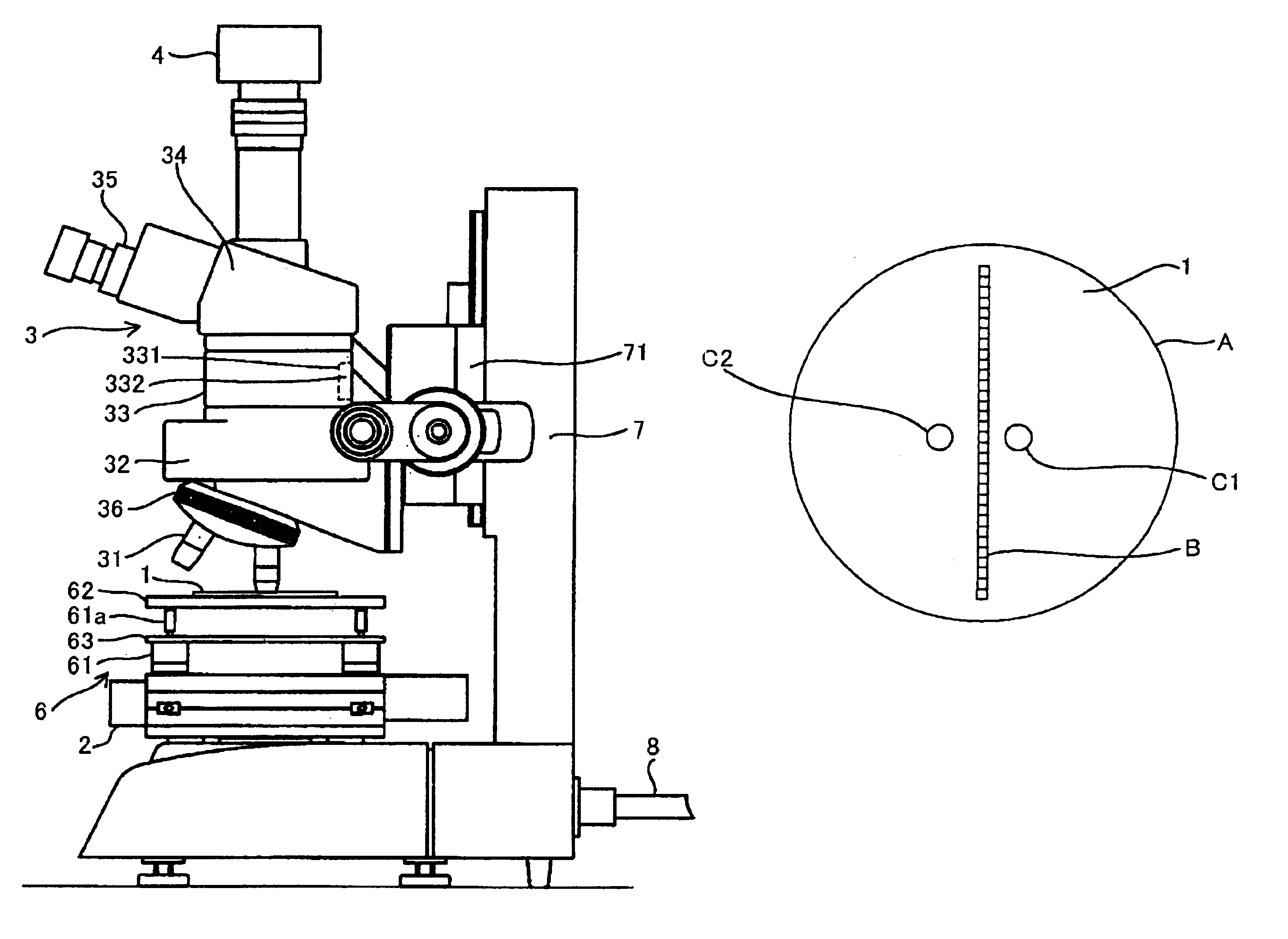
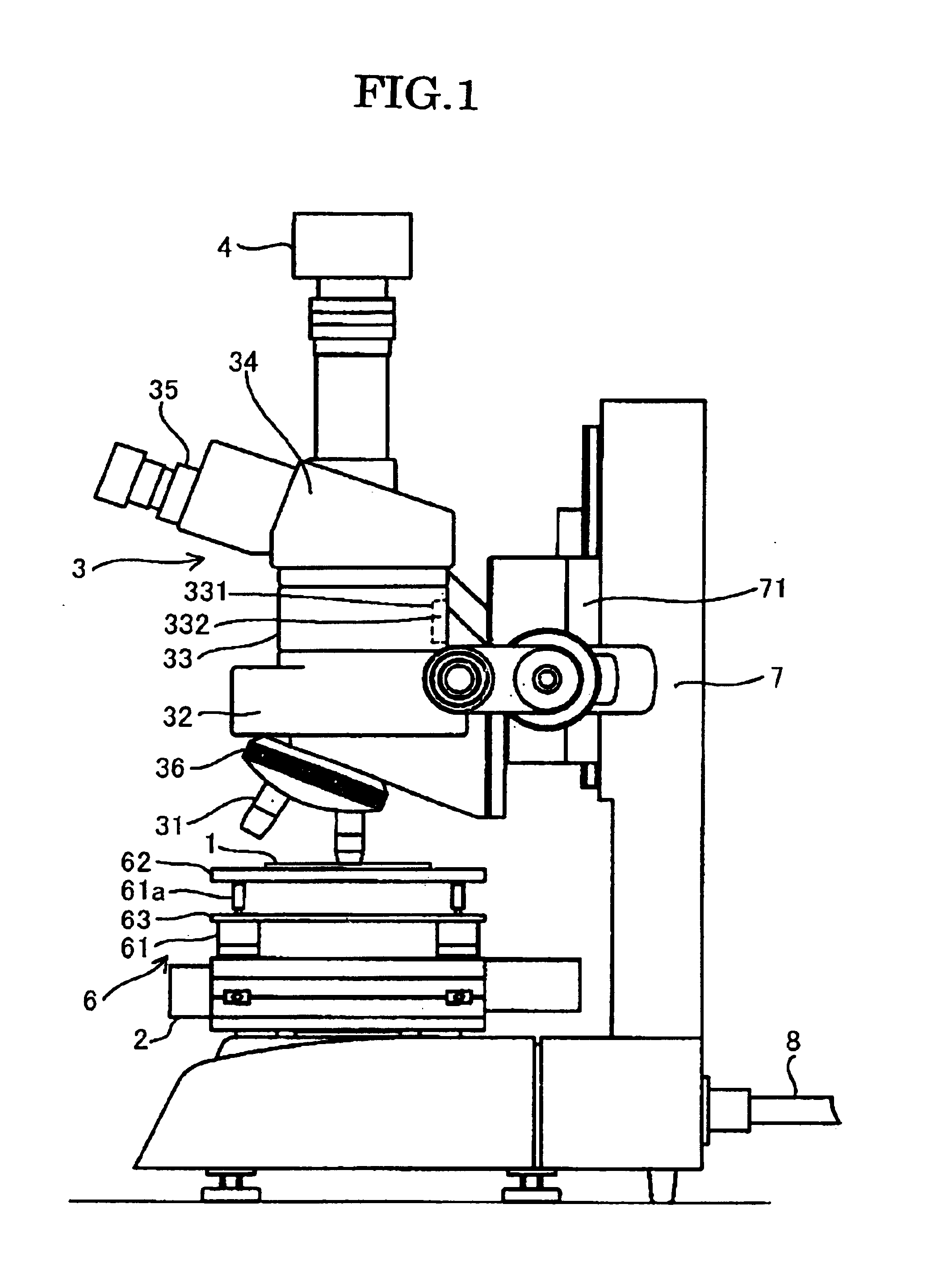
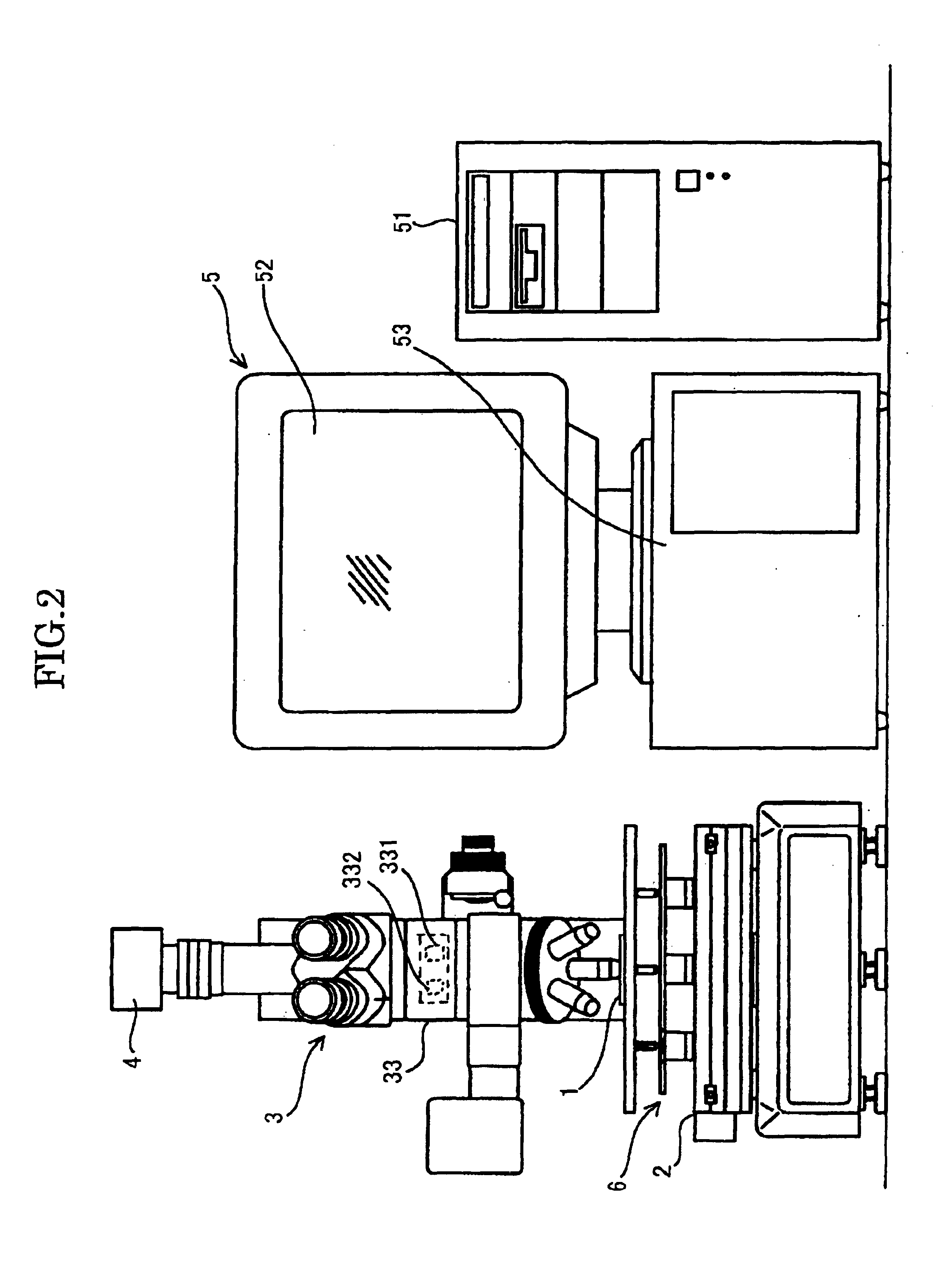
[0039]With reference to attached FIGS. 1 to 3, a microscope apparatus according to the present invention will be explained in connection with use as a radiation track detector. The radiation track detector has a moving means 2 for moving a track-detecting solid matter 1 serving as a sample, a microscope 3 for magnifying the track-detecting solid matter 1, a line sensor 4 for imaging the magnified solid matter 1 for track detection as a line image, and determining means 5 for preparing an image of the solid matter 1 for track detection from the line image and determining an amount and direction of incident radiation from the image.

[0040]The moving means 2 is provided with a tilting table 6 serving as a support base for supporting the track-detecting solid matter 1 and adjusting its inclination and focal length. The moving means 2 and the microscope 3 are respectively supported by a frame 7 having an L-shape. The moving means 2 is arranged on a horizontal part of the L-shaped frame 7 ...


PUM


Abstract

A microscope apparatus has a sample table for supporting a sample and being mounted to undergo movement in a horizontal direction. A line sensor acquires a line image for each of a series of measuring positions of the sample in accordance with movement of the sample at a constant speed by one measuring width of the line sensor in the horizontal direction. An image processing device produces an image of the sample based on the line images acquired by the line sensor. A focusing device has a light-projecting member for projecting light onto the sample at a position forward of a leading side of an imaging range of the line sensor in the horizontal direction to prevent light reflected by the sample as a result of the projected light from being incident on and interfering with the line images acquired by the line sensor.

Description

BACKGROUND OF THE INVENTION[0001]1. Field of the Invention[0002]The present invention relates generally to an imaging microscope and, more particularly, to a microscope for examining the amount and direction of incident radiation such as neutrons or the like, or for examining cellular tissue or other specimens in a hospital or laboratory environment, and which performs imaging of a sample using a line sensor.[0003]2. Discussion of Related Art[0004]In recent years, there has been an increase in the number and types of facilities which produce radiation for various reasons, such as hospitals, radiotherapy clinics, and atomic power plants. Associated with this increase is a heightened need for measuring personnel at such locations for exposure to harmful amounts of radiation.[0005]Conventionally, radiation exposure testing has involved attaching a sample material to a person's coat or other article of clothing to measure an amount of incident radiation on the sample, as disclosed in JP...

Claims


Application Information

Patent Timeline
IPC IPC(8): G02B21/24G02B21/36
CPCG02B21/241G02B21/365
Inventor YASUDA, NAKAHIROHONMA, YOSHIHIRO
Owner NAT INST OF RADIOLOGICAL SCI
Why Eureka
Try Eureka