Magnetic transfer apparatus

a transfer apparatus and magnetic field technology, applied in the field of magnetic transfer apparatus, can solve the problem of insufficient contact pressure, and achieve the effect of reducing the thickness of the lid and preventing the non-uniformity of contact pressure due to lid deformation

Inactive Publication Date: 2005-08-02
FUJIFILM HLDG CORP +1
View PDF3 Cites 0 Cited by
  • Summary
  • Abstract
  • Description
  • Claims
  • Application Information

AI Technical Summary

Benefits of technology

[0011]The second holder is preferably thicker in the peripheral portion than the central portion thereof. In this embodiment, non-uniformity of contact

Problems solved by technology

According to JP-A-11-25455, however, a sufficient contact pressure is not

Method used


Image

  • Magnetic transfer apparatus
  • Magnetic transfer apparatus
  • Magnetic transfer apparatus

Examples


Embodiment Construction

[0017]The present invention will further be illustrated with respect to its preferred embodiments by way of the drawings.

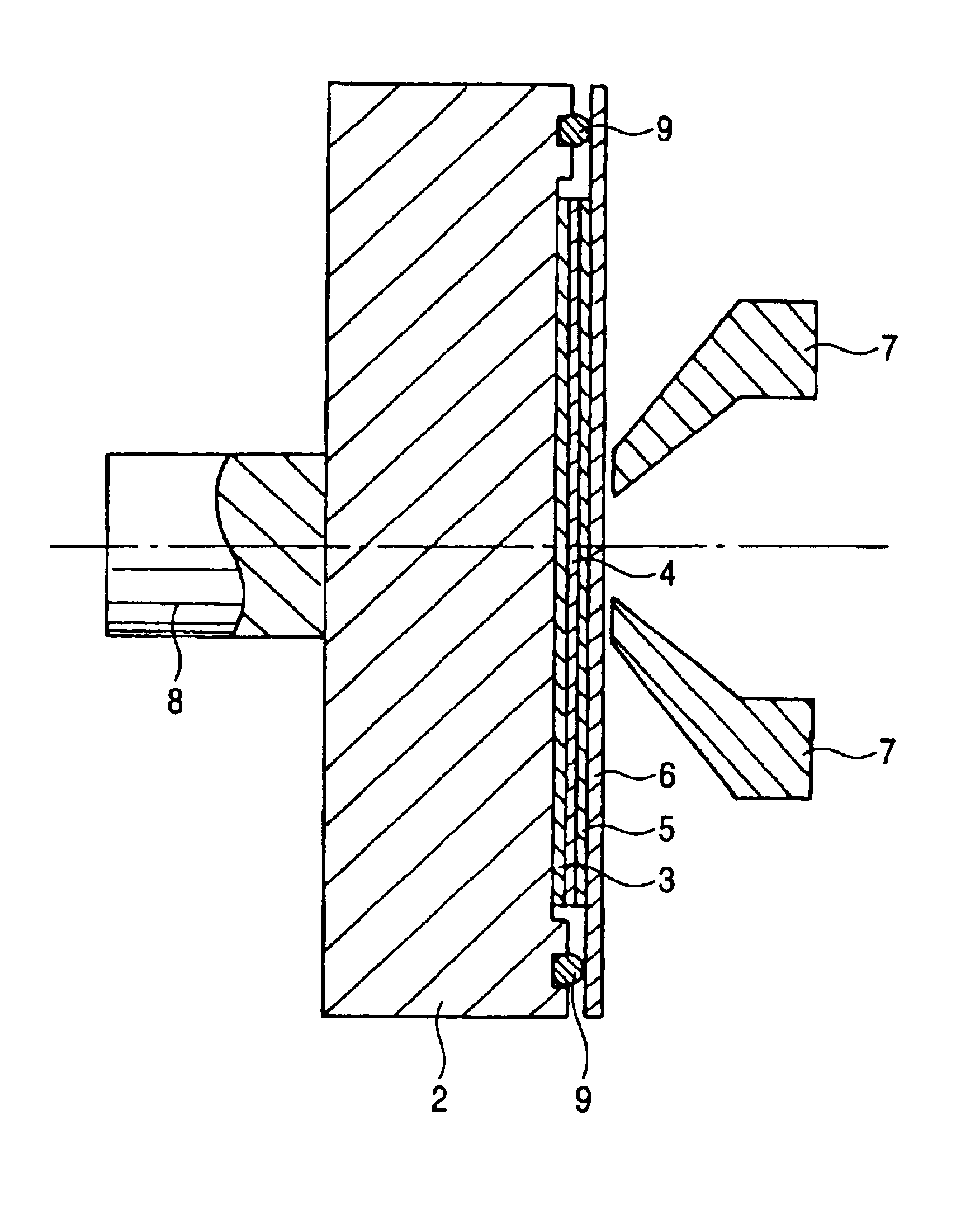
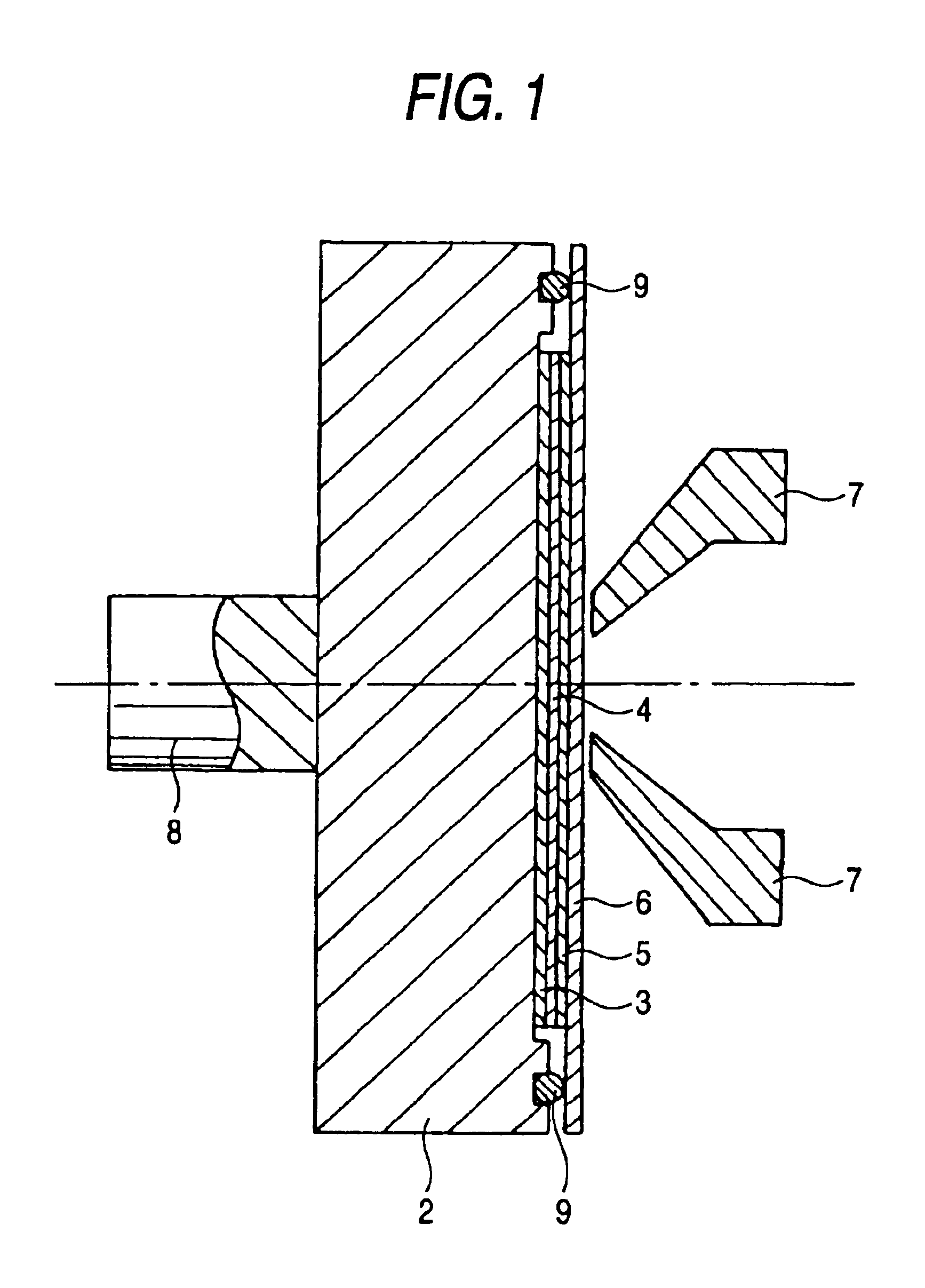
[0018]FIG. 1 is a cross-sectional view of a magnetic transfer apparatus according to one embodiment of the invention. The magnetic transfer apparatus shown in FIG. 1 has a first holder 2 for holding a pair of master disks 3, 5 and a slave disk 4 sandwiched between the pair of master disks 3, 5 by a suction mechanism (not shown), a plate-shaped lid 6 facing the first holder 2 as a second holder to form a closed space together with the holder 2, a pair of magnet (a head for magnetic field application) 7, 7 disposed by the side of the lid 6, a shaft 8 for supporting and rotating the holders during magnetic transfer, and an O-ring 9 for fixing the first holder 2 and the second holder 6 and shielding the closed space. In the closed space, a first master disk 3 is held to the first holder 2, a slave disk 4 is brought into intimate contact with the first master disk 3 in...


PUM


Abstract

A magnetic transfer apparatus for transferring patterned information formed on a surface of a master disk to a magnetic recording medium as a slave disk placed in intimate contact with the surface of the master disk by applying a magnetic field to the disks, which comprises: a magnet; a first holder for holding the master disk and the slave disk; and a second holder facing the first holder, the first holder being supported by a supporting member, the magnet being disposed on only an outer side of the second holder, and the second holder being formed solely of a lid.

Description

FIELD OF THE INVENTION[0001]This invention relates to a magnetic transfer apparatus for transferring patterned information formed on a master disk to a magnetic recording medium as a slave disk.BACKGROUND OF THE INVENTION[0002]Magnetic transfer is a technique for transferring information, such as survo information, from a master medium to the magnetic recording layer of a magnetic recording medium (hereinafter referred to as a slave medium or a slave disk) placed in close contact with the master medium by applying a magnetic field to the disks. The master medium carries thereon a pattern of fine unevenness formed of a magnetic substance in accordance with information to be transferred such as survo signals. A known apparatus for carrying out magnetic transfer is disclosed in JP-A-11-25455.[0003]FIG. 4 is a cross-sectional view of the magnetic transfer device of JP-A-11-25455. A vacuum pump 17 is operated with a valve 18 open to evacuate grooves 14 formed on a master disk 25. As a re...

Claims


Application Information

Patent Timeline
IPC IPC(8): G11B5/86G11B5/82
CPCB82Y10/00G11B5/743G11B5/865G11B5/82G01F23/42G01D13/12
Inventor ARAKI, MINORU
Owner FUJIFILM HLDG CORP
Why Eureka
Try Eureka