Hermetically sealed micro-device package using cold-gas dynamic spray material deposition
a micro-device package and material deposition technology, applied in the field of packaging methods, can solve the problems of increasing the cost of the overall package, affecting the overall package cost,
Inactive Publication Date: 2005-08-02
ASTRAVAC GLASS INC
View PDF16 Cites 81 Cited by
- Summary
- Abstract
- Description
- Claims
- Application Information
AI Technical Summary
Benefits of technology
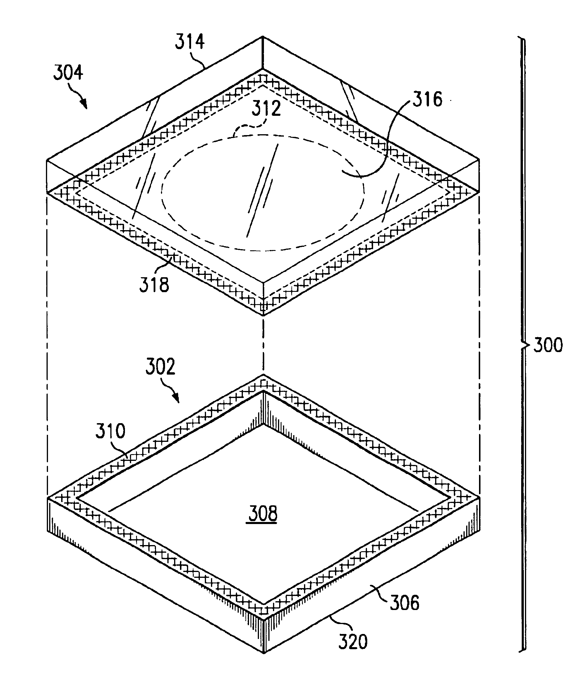
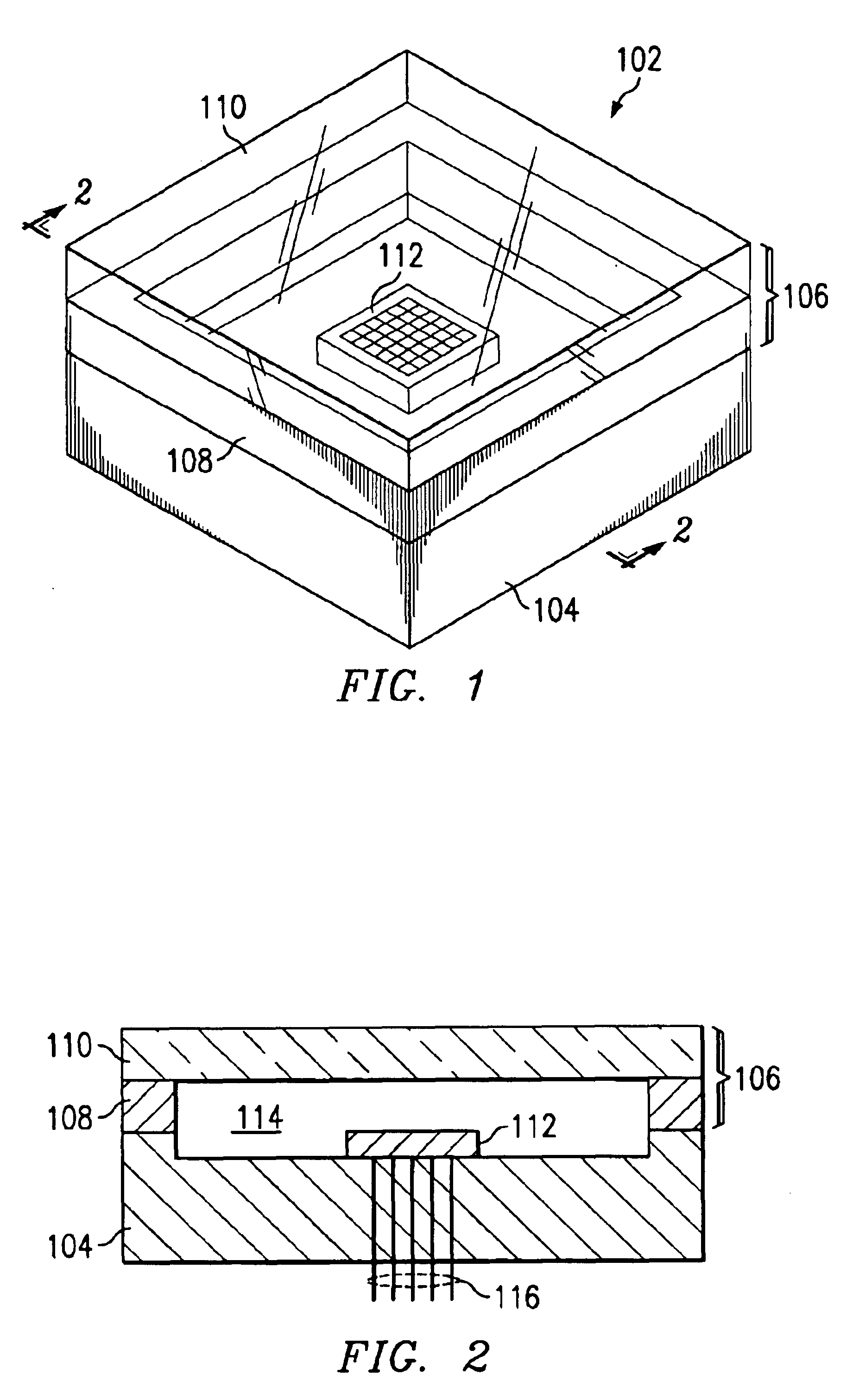
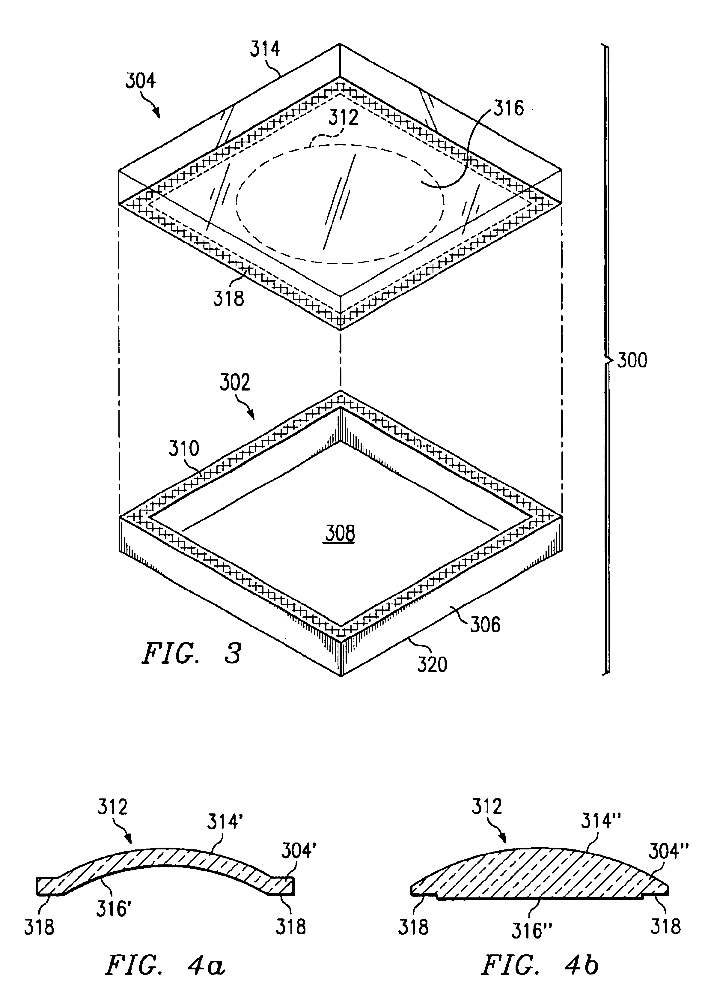
"The present invention is about a cover assembly that can be welded onto a micro-device package base to create a hermetically sealed micro-device package. The cover assembly includes a sheet of transparent material with a window portion and a built-up metallic frame adhering to the sheet. The metallic frame is formed by spraying powdered metal particles onto the sheet and then adding more powdered metal particles over the initial coating to create a continuous metallic coating that acts as the base of the frame. The cover assembly helps to protect the micro-device from environmental factors and ensures its proper functionality."
Problems solved by technology
However, because the fusing temperature is above TG, the original surface finish of the glass pane is typically ruined, making it necessary to finish or re-finish (e.g., grinding and polishing) both surfaces of the window pane after fusing in order to obtain the necessary optical characteristics.
This polishing of the window panes requires additional process steps during manufacture of the cover assemblies, which steps tend to be relatively time and labor intensive, thus adding significantly to the cost of the cover assembly, and hence to the cost of the overall package.
In addition, the need to polish both sides of the glass after fusing requires the glass to project both above and below the attached frame.
This restricts the design options for the cover assembly with respect to glass thickness, dimensions, etc., which can also result in increased material costs.
While the methods described above have heretofore produced useable window assemblies for hermetically sealed micro-device packages, the relatively high cost of these window assemblies is a significant obstacle to their widespread application.
Method used
View moreImage
Smart ImageViewing Examples
Examples
example 1
[0060]
LayersMetalDepositionMin. (microns)Max. (microns)1AlCVD, PVD0.763.5
example 2
[0061]
LayersMetalDepositionMin. (microns)Max. (microns)1AlCVD, PVD0.002252CuCVD, PVD, SBP0.0026.353NiCVD, PVD, SBP0.0026.354Sn orCVD, PVD, SBP0.763.5SnBi
example 3
[0062]
LayersMetalDepositionMin. (microns)Max. (microns)1AlCVD, PVD0.002252ZnCVD, PVD, SBP0.0026.353NiCVD, PVD, SBP0.0026.354Sn orCVD, PVD, SBP0.763.5Sn—Bi
Login to View More PUM
| Property | Measurement | Unit |
|---|---|---|
| thickness | aaaaa | aaaaa |
| TG | aaaaa | aaaaa |
| temperatures | aaaaa | aaaaa |
Abstract
A cover assembly for welding to a package base to form a hermetically sealed micro-device package. The cover assembly includes a sheet of a transparent material having a window portion. A built-up metallic frame adheres to the sheet and circumscribes the window portion, the frame having been deposited as follows: First, powdered metal particles are sprayed onto a prepared area of the sheet using a gas jet at a temperature below the fusing temperature of the particles, the jet having a velocity sufficient to cause the particles to merge with one another upon impact with the sheet and with one another to form an initial continuous metallic coating adhering to the prepared area of the sheet. Next, successive metal particles are applied over the initial coating using the jet to form the frame incorporating the initial continuous metallic coating as its base and having an predetermined overall thickness.
Description
CROSS-REFERENCE TO RELATED APPLICATIONS[0001]This application is a Divisional of U.S. patent application Ser. No. 10 / 133,049 filed on Apr. 26, 2002, now U.S. Pat. No. 6,723,379 which is a Continuation-In-Part of U.S. patent application Ser. No. 10 / 104,315 filed Mar. 22, 2002, now U.S. Pat. No. 6,627,814.TECHNICAL FIELD OF THE INVENTION[0002]The current invention relates to packages for photonic devices, optical devices, micro-mechanical devices, micro-electromechanical systems (MEMS) devices or micro-optoelectromechanical systems (MOEMS) devices, and more particularly, to methods for manufacturing packages having a hermetically sealed chamber covered by a transparent window using cold-gas dynamic spray material deposition.BACKGROUND OF THE INVENTION[0003]Photonic, optical and micro-mechanical devices are typically packaged such that the active elements (i.e., the emitters, receivers, micro-mirrors, etc.) are disposed within a sealed chamber to protect them from handling and other en...
Claims
Login to View More Application Information
Patent Timeline
 Patent Type & Authority Patents(United States)
IPC IPC(8): B05D5/12G06F1/16B05D1/12B81B7/00E06B3/26H01L23/02H01L23/04H01L27/146H01L31/0203H01L31/0232H02G3/08H05K5/06
CPCB81B7/0067B81C1/00269B81C1/00293H01L21/50H01L23/10H01L27/14618H01L27/14625H01L27/14683H01L27/14685H01L31/0203H01L31/0232Y10T29/49002H01L2924/09701H01L2924/0002B81B2201/047H01L2924/00Y02P80/30H01L31/02325
Inventor STARK, DAVID H.
Owner ASTRAVAC GLASS INC
Features
- R&D
- Intellectual Property
- Life Sciences
- Materials
- Tech Scout
- Unparalleled Data Quality
- Higher Quality Content
- 60% Fewer Hallucinations
Learn More Browse by: Latest US Patents, China's latest patents, Technical Efficacy Thesaurus, Application Domain, Technology Topic, Popular Technical Reports.
© 2025 PatSnap. All rights reserved.Legal|Privacy policy|Modern Slavery Act Transparency Statement|Sitemap|About US| Contact US: help@patsnap.com


