
Optical head device and optical disk unit capable of stable signal reproduction

a technology of optical disk unit and optical head, which is applied in the field of optical head, can solve the problems of difficult to ensure stable reproduction and light amount emitted from the objective lens change, and achieve the effect of stable signal reproduction

Inactive Publication Date: 2005-08-02
KK TOSHIBA
View PDF6 Cites 5 Cited by
  • Summary
  • Abstract
  • Description
  • Claims
  • Application Information

AI Technical Summary

Benefits of technology

The present invention provides an optical head and an optical disk unit that can ensure stable signal reproduction. The optical head includes a light emitting unit, a focusing unit, a wavefront transforming optical element, a thickness difference detection unit, a wavefront transforming optical element control unit, a beam splitter, a light detector, an output control unit, a motor, and a control unit. The optical disk unit includes an information recording layer and a light transmission layer for protecting the information recording layer. The invention solves the problem of thickness error in the light transmission layer of the optical disk. The technical effects of the invention include stable signal reproduction, improved signal quality, and reduced noise.

Problems solved by technology

This causes a problem in the case where light amount is set during reproduction in particular.
That is, when the collimator lens is moved in an optical axis direction in order to correct the spherical aberration caused by the thickness error of the light transmission layer, it is known that a quantity of light incident to the objective lens changes, and thus, the light amount emitted from the objective lens changes, making it difficult to ensure stable reproduction.

Method used


Image

  • Optical head device and optical disk unit capable of stable signal reproduction
  • Optical head device and optical disk unit capable of stable signal reproduction
  • Optical head device and optical disk unit capable of stable signal reproduction

Examples


first embodiment

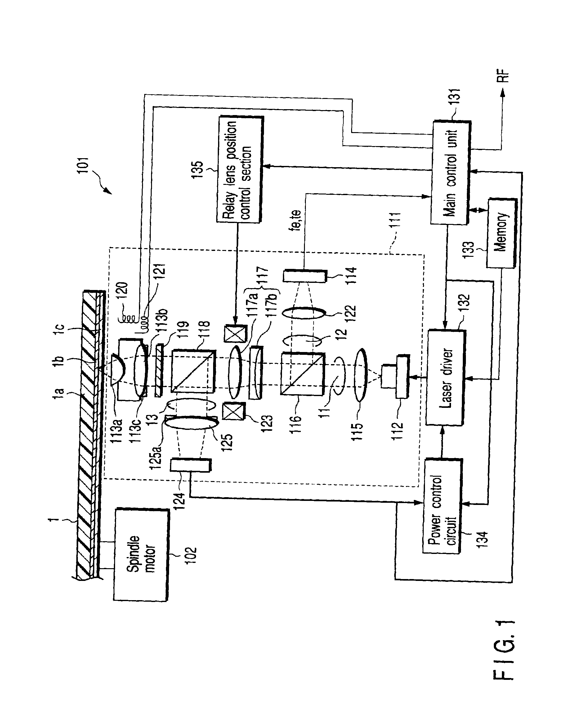
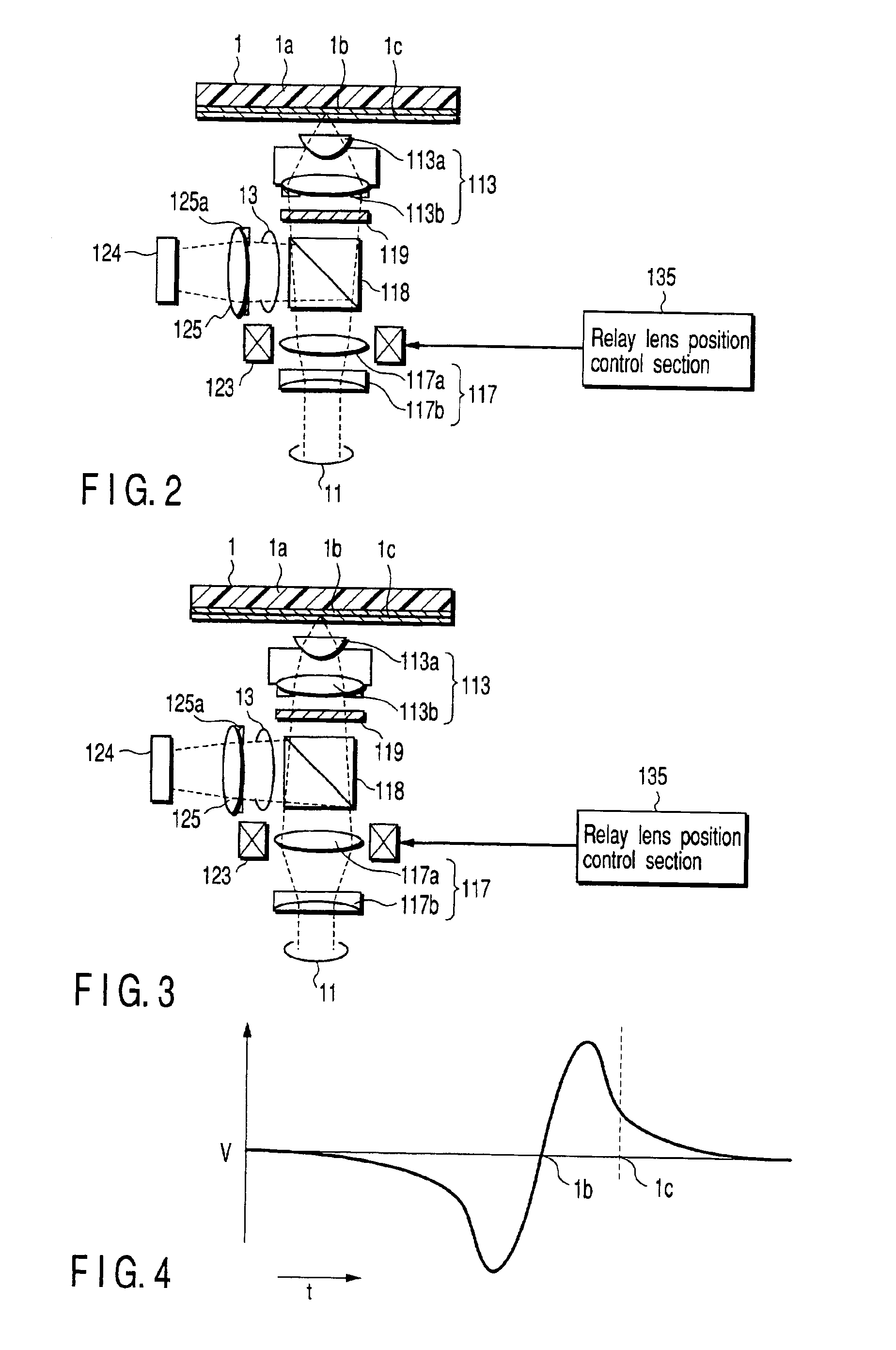
[0078]In the first embodiment shown in FIG. 1 to FIG. 3, there has been illustrated an example of detecting the thickness of the light transmission layer 1c before the optical disk 1 rotates. However, for example, an information indicating, for indicating a change in thickness of the light transmission layer 1c, is recorded in advance in a predetermined region of the recording layer 1b of the optical disk 1, whereby, prior to recording or reproduction, the information indicating a change in thickness of the light transmission layer 1c is read, and a position of the convex lens 117a of the relay lens 117 may be controlled so as to offset an effect of the thickness error of the light transmission layer in a region or at a position where the thickness of the light transmission layer 1c changes.

[0079]In addition, in the above described embodiment, there has been illustrated an example of a method for correcting a change in light amount of the laser beam caused by the thickness error of ...

second embodiment

[0082]Now, the optical disk unit according to the present invention will be described with reference to FIGS. 6A and 6B. Like elements of the optical disk unit shown in FIG. 1 are designated by like reference numerals. A detailed description is omitted here.

[0083]In an optical disk unit 301 shown in FIGS. 6A and 6B, the third laser beam 13, split from the laser beam 11 oriented to the optical disk 1 by a second beam splitter 318, is focused to a light detector 361 in which an aperture 361a of a predetermined size is integrally provided on a light incident face thereon. The size of a light detection region (light receiving face) 361b of the light detector 361 is defined to be smaller as compared with the laser beam 11 of which a predetermined sectional shape (area) is provided by the relay lens 117. That is, on the light receiving face 361b of the light detector 361, advantageous effect of an opening restriction is attained by the aperture 361a.

[0084]In this way, in the optical disk...

third embodiment

[0087]Now, the optical disk unit according to the present invention will be described with reference to FIG. 7. Like elements of the optical disk unit shown in FIG. 1 (FIGS. 6A and 6B) are designated by like reference numerals. A detailed description will be omitted.

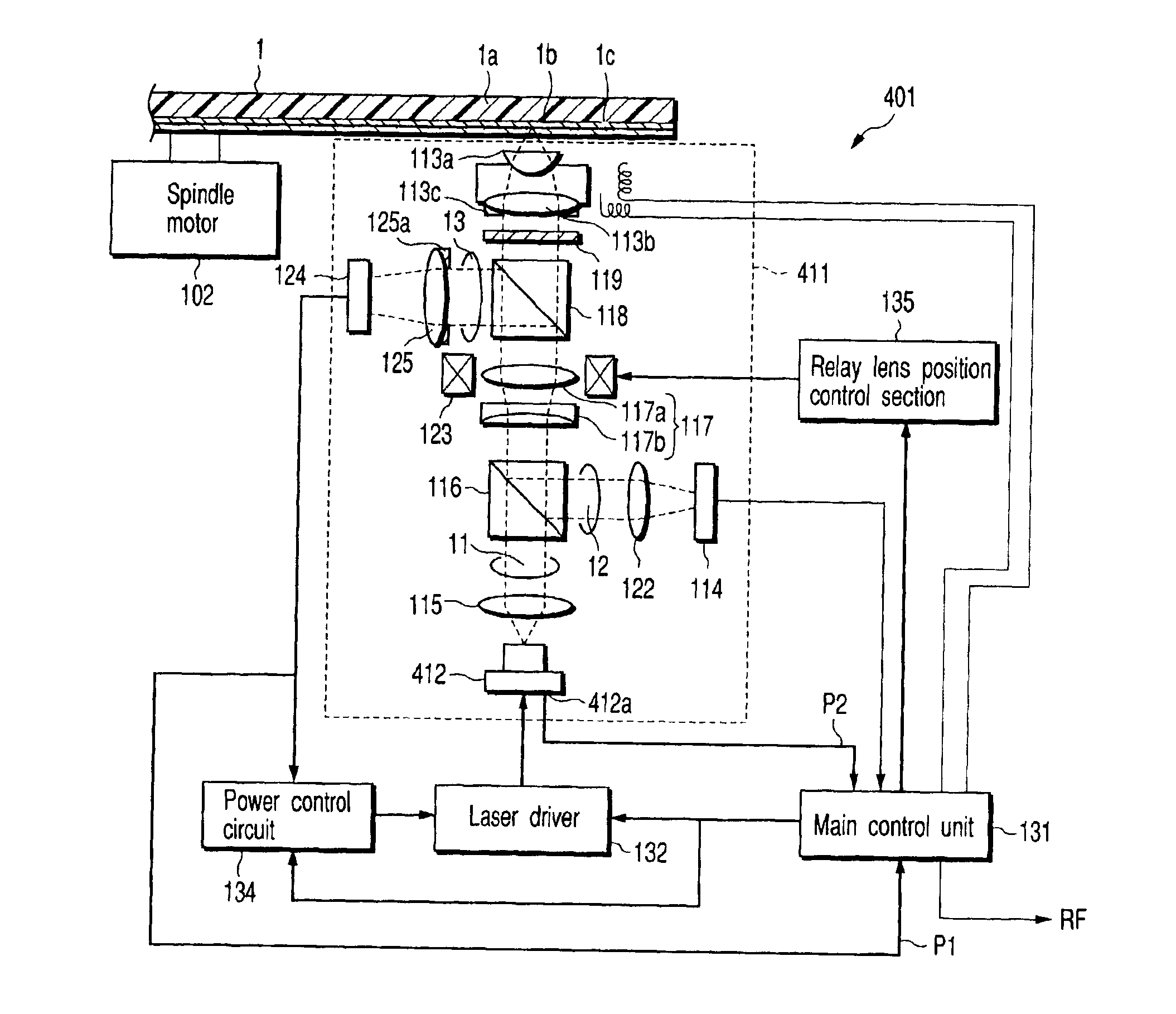
[0088]An optical disk unit 401 shown in FIG. 7 is characterized in that an output signal from a back monitor element 412a incorporated in advance in a laser unit 412, the back monitor element outputting a current proportional to the light amount of the laser beam 11 radiated by the laser unit 412, is fed back to the main control circuit 131 independent of a power control circuit 134.

[0089]As shown in FIG. 7, to the main control circuit 131, there are inputted a first power monitor signal P1 produced when the light amount of the third laser beam 13 split from the laser beam 11 oriented to the optical disk 1 by an APC detecting system, i.e., the second beam splitter 118 is detected by the second light detector 124, and a b...


PUM

PropertyMeasurementUnit
thicknessaaaaaaaaaa
thicknessaaaaaaaaaa
wavelengthaaaaaaaaaa

Abstract

The present invention relates to an optical head unit and an optical disk unit using the optical head unit. The head unit includes a wavefront transforming optical element control unit to controls a wavefront transforming optical element so as not to transform wavefront of a light beam focused on a recording layer by a focusing unit due to the thickness error of a light transmission layer positioned between the recording layer and the focusing unit based on an electrical signal outputted from a first light detector, and an output control unit that controls light amount of a light beam radiated by a light emitting unit based on the magnitude of the electrical signal outputted from the light detector.

Description

CROSS-REFERENCE TO RELATED APPLICATIONS[0001]This application is based upon and claims the benefit of priority from the prior Japanese Patent Application No. 2001-294849, filed Sep. 26, 2001, the entire contents of which are incorporated herein by reference.BACKGROUND OF THE INVENTION[0002]1. Field of the Invention[0003]The present invention relates to an optical head for recording information into an optical disk and reproducing information from the optical disk and an optical disk unit having the optical head. In addition, the present invention relates to a method for eliminating an effect of a spherical aberration caused by the thickness error of a surface resin layer of an optical disk.[0004]2. Description of the Related Art[0005]In an optical head and an optical disk unit, in order to improve efficiency of utilizing light, there has been proposed a method and apparatus for reducing an effect of spherical aberration caused by the thickness error of a surface resin layer (light t...

Claims


Application Information

Patent Timeline
Patent Type & Authority Patents(United States)
IPC IPC(8): G11B7/125G11B7/004G11B7/135G11B7/00G11B7/13G11B7/09G11B7/1263G11B7/1369G11B7/1372G11B7/1378G11B7/1381G11B7/1392
CPCG11B7/1263G11B7/1369G11B7/1378G11B7/1381G11B7/13927G11B7/0948G11B2007/13727
Inventor KUWAHARA, MAHOIWATA, KATSUOTAKEHARA, SHINTAROMARUYAMA, SUMITAKA
Owner KK TOSHIBA
Learn More