Thermal type flow rate measuring apparatus

a flow rate and apparatus technology, applied in the direction of machines/engines, electrical control, instruments, etc., can solve the problems of complex circuit structure, change in resistance value of heat generating resistor itself, and complex sensor structure, so as to simplify manufacturing steps

Inactive Publication Date: 2005-08-09
HITACHI ASTEMO LTD
View PDF3 Cites 15 Cited by
  • Summary
  • Abstract
  • Description
  • Claims
  • Application Information

AI Technical Summary

Benefits of technology

[0012]In addition, recently, a demand for protection against electromagnetic interference has enlarged and the necessity of improving durability against electromagnetic interference has increased.
[0022]As a result, operations, such as laser trimming, for adjusting the heating temperature of the heat generating resistor, which have been required in the past, are no longer required, and manufacturing steps can be simplified.

Problems solved by technology

The related art, however, has a problem that the resistance value of a heat generating resistor itself is changed with heating of the heat generating resistor, which is formed in a thin wall portion.
However, such a proposal raises problems that the circuit structure is complicated and the sensor structure is also complicated.
Further, no considerations are paid to time-dependent changes of parts mounted on a circuit board.

Method used


Image

  • Thermal type flow rate measuring apparatus
  • Thermal type flow rate measuring apparatus
  • Thermal type flow rate measuring apparatus

Examples


Embodiment Construction

[0047]Preferred embodiments of the present invention will be described below with reference to the drawings.

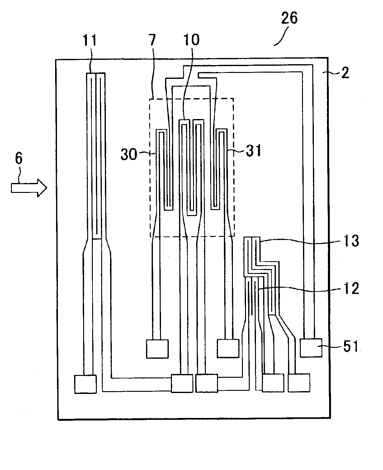
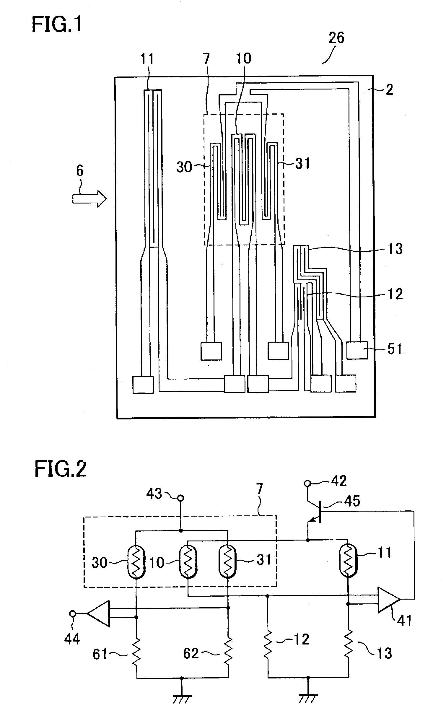
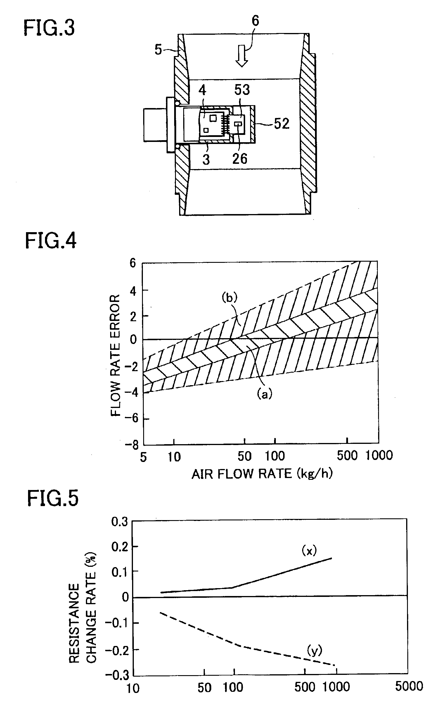
[0048]FIG. 1 is a diagram showing a structure and a wiring pattern of a thermal type flow sensor 26 used in a thermal type flow measuring apparatus 1 according to one embodiment of the present invention. FIG. 2 is a circuit diagram including the thermal type flow sensor 26 shown in FIG. 1. FIG. 3 is a sectional view showing a state in which the thermal type flow measuring apparatus 1 is actually mounted in an intake pipe of an internal combustion engine. A description is made of one embodiment of the present invention with reference to FIGS. 1, 2 and 3.

[0049]As shown in FIG. 1, the thermal type flow sensor 26 is of a structure that a thin wall portion 7 is formed in a substrate 2 of a semiconductor, etc., and a heat generating resistor 10, an upstream-side temperature sensor 30 and a downstream-side temperature sensor 31 are arranged in the thin wall portion 7 to be thermally ...


PUM


Abstract

A flow rate sensor has a problem that a resistance value of a heat generating resistor itself varies and sensor characteristics are changed during use of the sensor for a long term. Also the temperature of the heat generating resistor must be adjusted on a circuit substrate with a resistance constituting one side of a fixed temperature difference control circuit, and this has been one of factors pushing up the production cost. All resistances used for fixed temperature difference control are formed on the same substrate as temperature sensitive resistors of the same material. This enables all the resistances for the fixed temperature difference control to be exposed to the same environmental conditions. Hence, even when the resistances change over time, the changes over time occur substantially at the same tendency. Since the resistances for the fixed temperature difference control change over time essentially at the same rate, a resulting output error is very small.

Description

BACKGROUND OF THE INVENTION[0001]1. Field of the Invention[0002]The present invention relates to a apparatus for detecting a flow rate, and more particularly to, for example, a flow sensor for use in an internal combustion engine or a flow sensor for use in a fuel battery system.[0003]2. Description of the Related Art[0004]Hitherto, as air flow sensors disposed in intake air passages of internal combustion engines of automobiles, etc. for measuring the amounts of intake air, thermal ones have been primarily employed because of a capability of directly detecting air mass flow rates. Recently, air flow sensors manufactured by semiconductor micromachining techniques, in particular, have received attention because they have a high-speed response and are able to detect a back flow by utilizing the high-speed response.[0005]One example of the conventional technique regarding such a thermal type air flow sensor using a semiconductor substrate is disclosed in, e.g., Japanese Publication of ...

Claims


Application Information

Patent Timeline
Patent Type & Authority Patents(United States)
IPC IPC(8): G01F1/696G01F1/684G01F1/698G01F1/692F02D35/00F02D41/18F02D45/00G01F1/699
CPCG01F1/6842G01F1/6845G01F1/692G01F1/698G01F1/699
Inventor WATANABE, IZUMIHORIE, JUNICHINAKADA, KEIICHIUEYAMA, KEIYAMADA, MASAMICHI
Owner HITACHI ASTEMO LTD
Why Eureka
Try Eureka