Continuous two-dimensional corneal topography target

a topography target and two-dimensional technology, applied in the field of eye examination, can solve the problems of not becoming popular in commercial systems, difficult to know the exact point correspondence between a point on the reflected pattern source and its image reflected off the cornea, and the set of point correspondences that are not always correct, so as to improve surface reconstruction and image processing. robust

Inactive Publication Date: 2005-08-09
Z OPTICS INC
View PDF5 Cites 18 Cited by
  • Summary
  • Abstract
  • Description
  • Claims
  • Application Information

AI Technical Summary

Benefits of technology

[0006]The aim of this invention is to provide a means to generate a continuous two-dimensional reflection pattern suitable for corneal topography that uses sinusoidal profiles of both intensity and color values. The benefits of this technique are more robust image processing due to the ability to apply digital band pass filters, continuous data for improved surface reconstruction, and the ability to directly measure the meridian of the reflection pattern source point when the corneal surface normal does not lie in the meridian of the measurement instrument.

Problems solved by technology

One problem with concentric ring patterns is that it is difficult to know the exact point correspondence between a point on the reflected pattern source and its image reflected off the cornea.
To directly measure the point correspondence, polar and rectangular checkerboard patterns have also been proposed, but have not become popular in commercial systems.
The results of the computer image processing can yield a set of point correspondences that is not always correct.
Such image processing errors would lead to large measurement errors in subsequent reconstruction processing.
Generally, if the discrete points are far apart the reconstruction error will be larger than would be obtained if the points were close together.

Method used


Image

  • Continuous two-dimensional corneal topography target
  • Continuous two-dimensional corneal topography target
  • Continuous two-dimensional corneal topography target

Examples


Embodiment Construction

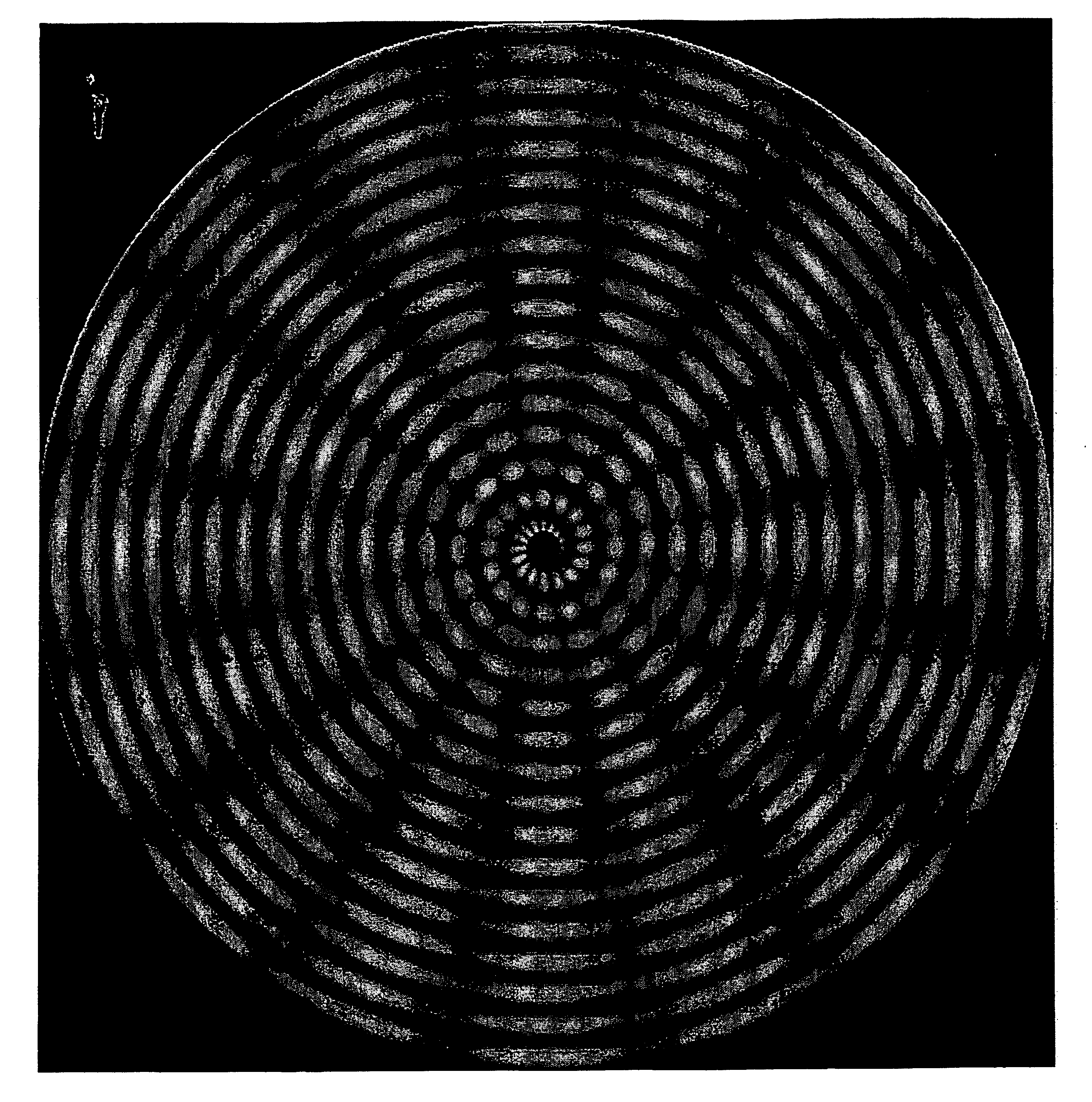
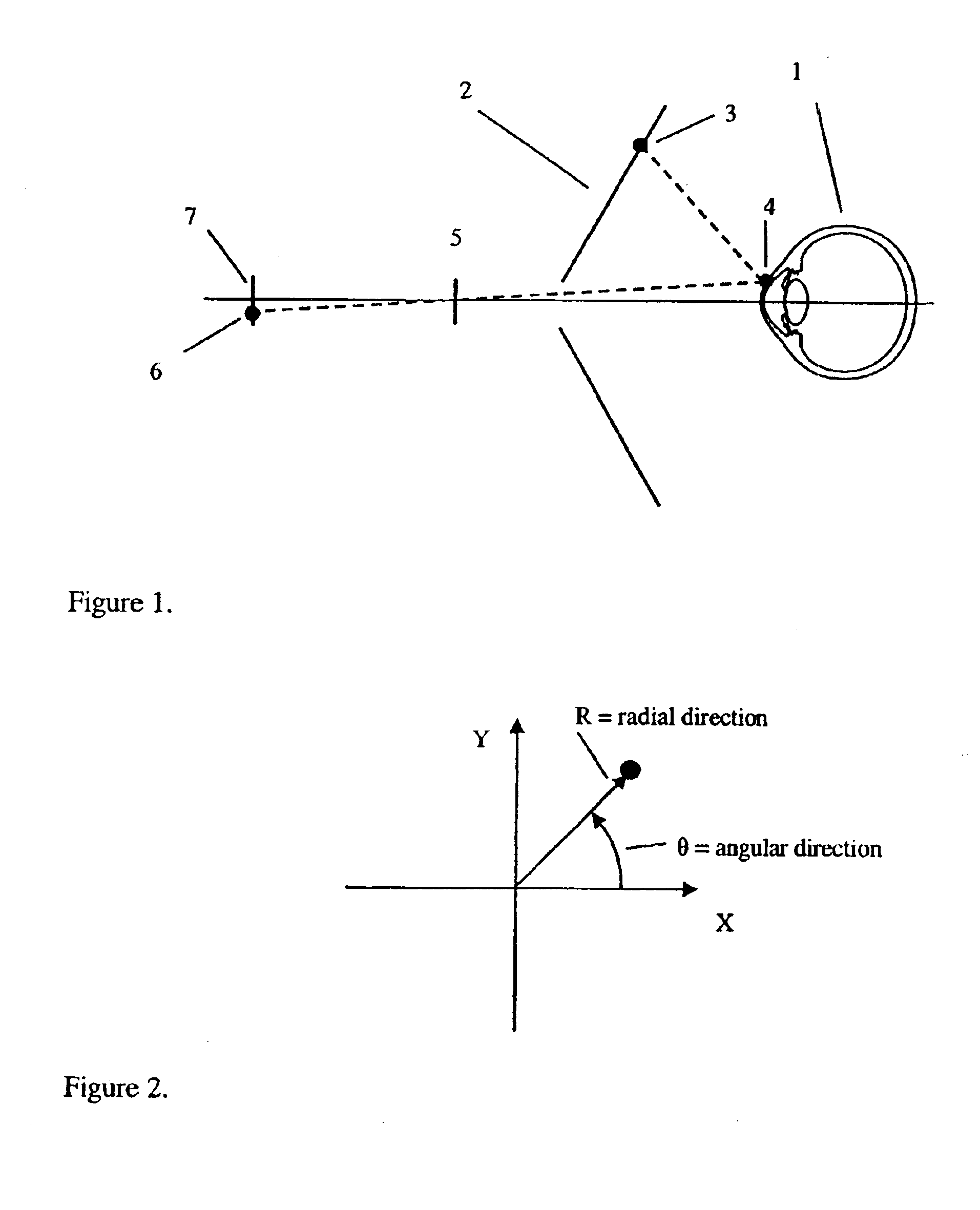
[0014]The basic geometry for a reflection based corneal topography system is illustrated in FIG. 1. The eye 1 is positioned in front of the reflection pattern source 2. A point 3 on the reflection source reflects off the cornea at corneal surface point 4 and is focused by lens 5 onto CCD sensor 7 at digital image point 6. The proposed reflection pattern consists of three parts: the radial intensity profile, the angular color profile, and the contrast control.

Radial Intensity Profile

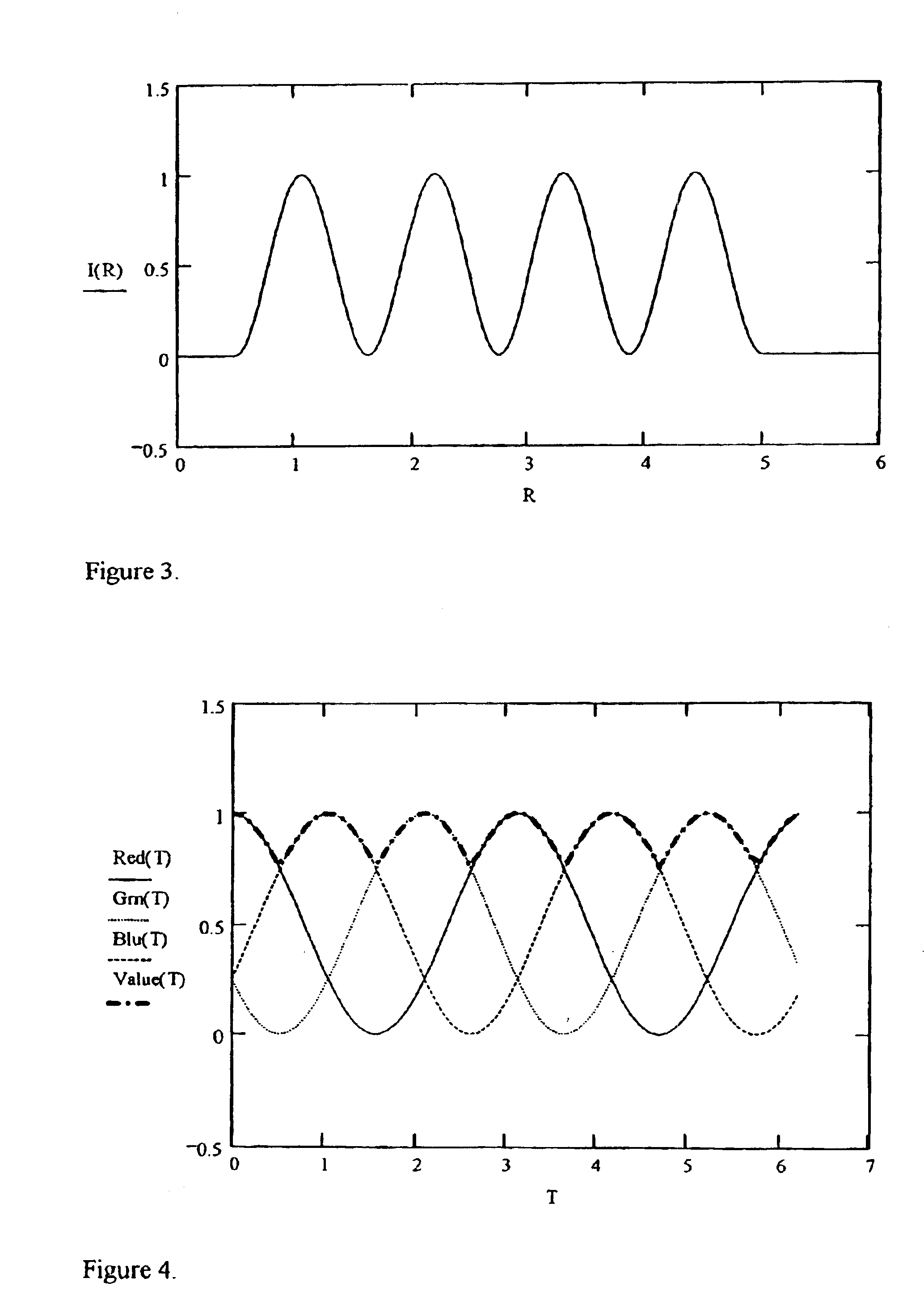
[0015]The radial intensity profile is given by equation (1). I⁡(r,t)={0rr⁢ ⁢0cos⁡[(r-r⁢ ⁢0)×2⁢ ⁢π×N⁢ ⁢rr⁢ ⁢Max-r⁢ ⁢0+t×N⁢ ⁢t+π]2+12r⁢ ⁢0rr⁢ ⁢Max0r>r⁢ ⁢Max

where[0016]r0=radial starting point (mm)[0017]rMax=radial ending point (mm)[0018]Nr=radial cycles[0019]Nt=spiral cycles

[0020]The center of the radial intensity profile is set to zero to correspond to the aperture at the reflective pattern source 2 indicated in FIG. 1. The profile is zero for radial distances up to r0 mm. For radial distance values from r...


PUM

PropertyMeasurementUnit
angular coloraaaaaaaaaa
spatial frequencyaaaaaaaaaa
powers of sinusoidsaaaaaaaaaa

Abstract

A means to generate a continuous two-dimensional reflection pattern suitable for corneal topography that uses sinusoidal profiles of both intensity and color values. The technique provides a more robust image processing due to the ability to apply digital band pass filters, continuous data for improved surface reconstruction, and the ability to directly measure the meridian of the reflection pattern source point when the corneal surface normal does not lie in the meridian of the measurement instrument.

Description

RELATED APPLICATIONS[0001]This application is a continuation of U.S. Provisional Application 60 / 382,722 filed May 24, 2002 and claims priority thereto.FIELD OF THE INVENTION[0002]This invention is directed to the field of eye examination.BACKGROUND OF THE INVENTION[0003]The human cornea provides about two-thirds of the refraction of the eye. Thus, its shape is of great interest to optometrists and ophthalmologists who must provide a patient with sharp vision. A device that measures the shape of the cornea is referred to as a corneal topographer. Although there are various methods to measure the cornea, the most popular commercial systems are based on the principle of measuring a pattern reflected off the cornea. The pattern most often used for this purpose is a set of concentric rings. One problem with concentric ring patterns is that it is difficult to know the exact point correspondence between a point on the reflected pattern source and its image reflected off the cornea. If the ...

Claims


Application Information

Patent Timeline
Patent Type & Authority Patents(United States)
IPC IPC(8): A61B3/107A61P31/04A61P31/12C07K9/00C07K14/47C07K14/73C07K14/75C07K16/00
CPCA61B3/107A61P31/04A61P31/12
Inventor SARVER, EDWIN J.
Owner Z OPTICS INC
Why Eureka
Try Eureka