Minimally invasive valve repair procedure and apparatus

a valve and minimally invasive technology, applied in mechanical equipment, surgical staples, veterinary instruments, etc., can solve the problems of long recovery time, cumbersome suture management, knot tying pain, etc., and achieve the effect of reducing the distance of separation

Inactive Publication Date: 2005-08-09
MEDTRONIC INC
View PDF42 Cites 329 Cited by
  • Summary
  • Abstract
  • Description
  • Claims
  • Application Information

AI Technical Summary

Benefits of technology

[0005]Methods and apparatus embodying this invention with which the above and other objects can be accomplished are characterized as using a clip of a self-closing type as a tissue connector to capture leaflets and secure them together. Such a clip is typically U-shaped, having two end points, when it is constrained to be in an open configuration but is made of a wire of a shape memory material such that it tends to coil up to assume its natural closed configuration. Thus, if such a clip is placed between a pair of valve leaflets to be repaired, having each of its end points penetrating and completely passing through a different one of the leaflets while being constrained to be in its open configuration, and if the constraint which has been keeping the clip in its open configuration is then removed, it naturally tends to coil up, although it will not come to assume its natural closed configuration because it is hooked to the leaflets, tending nevertheless to reduce the distance of separation between its two end points. This has the effect of holding the leaflets together.

Problems solved by technology

Cumbersome suture management, knot tying pain and long recovery time are inherent to such open surgical procedures.

Method used


Image

  • Minimally invasive valve repair procedure and apparatus
  • Minimally invasive valve repair procedure and apparatus
  • Minimally invasive valve repair procedure and apparatus

Examples


Embodiment Construction

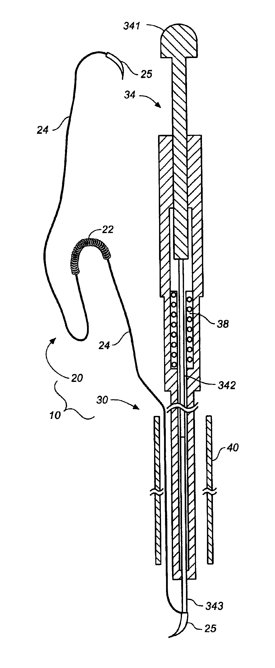
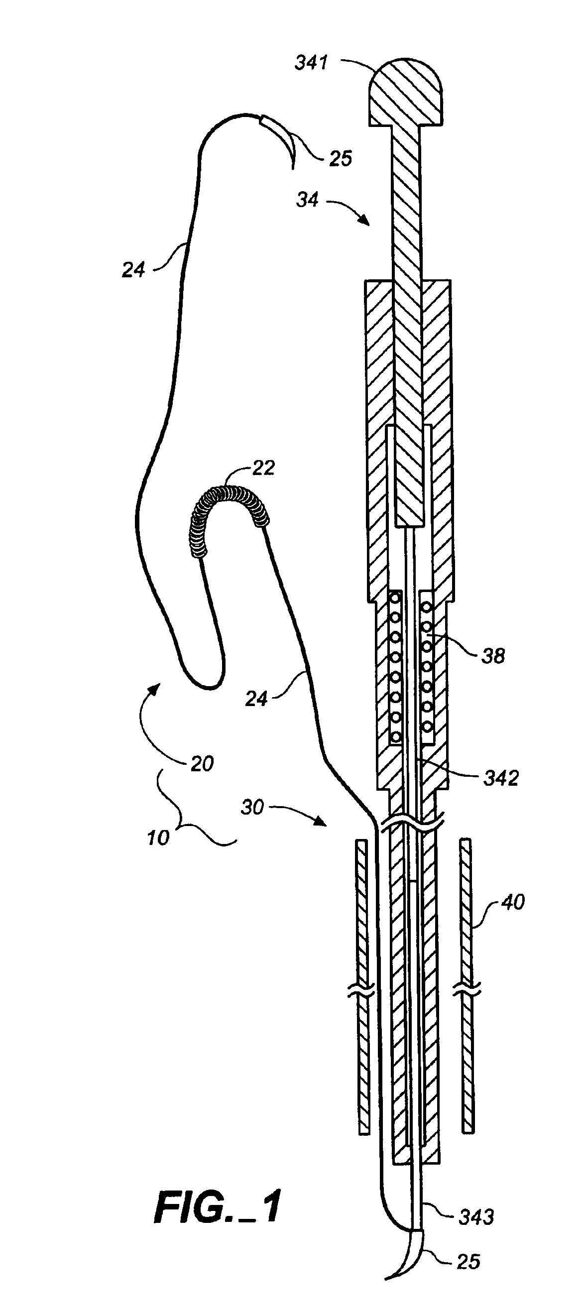
[0018]The invention is described next by way of examples. FIG. 1 shows schematically a tissue-connector apparatus 10 embodying this invention for a minimally invasive procedure. Described briefly, the apparatus 10 consists of a clip assembly 20 and a needle holder 30, which will be described next sequentially in detail.

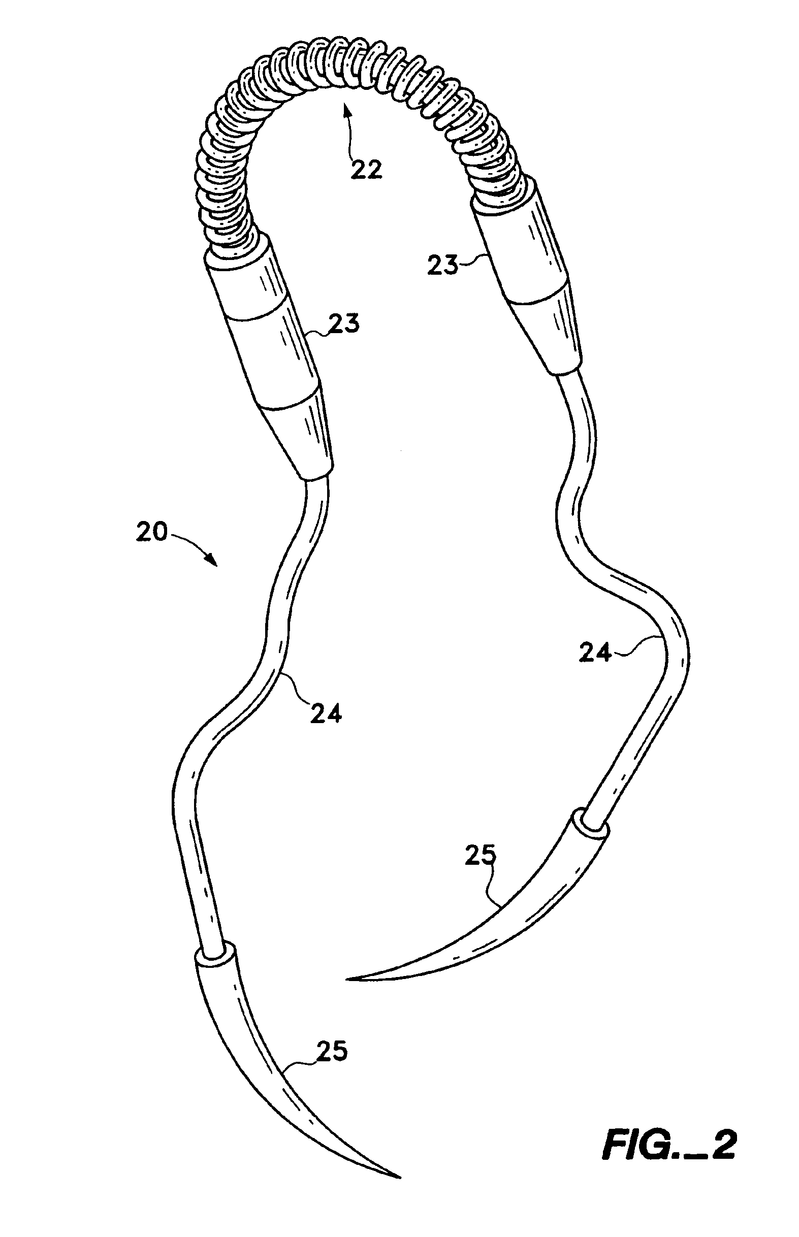
[0019]The clip assembly 20 according to this embodiment may be referred to as the double-arm clip assembly, characterized as having a clip 22 of a self-closing type with two end points each connected through a flexible member 24 such as a suture to a tissue penetrating needle 25 (as disclosed, for example, in aforementioned U.S. patent application Ser. Nos. 09 / 259,705, now U.S. Pat. No. 6,514,265, and 09 / 260,623, now U.S. Pat. No. 6,613,059, both filed Mar. 1, 2000, both of which applications are herein incorporated by reference). Each of the needles 25 has a tissue-piercing sharp point and is connected to a corresponding one of the flexible members 24. As shown more ...


PUM


Abstract

A clip of a self-closing type is used for valve repair. The clip is generally U-shaped with two end points separated from each other when it is constrained to be in an open configuration, but tends to coil up to assume its natural closed configuration if the constraint is removed. At least one end point is connected through a suture to a tissue-penetrating needle. A needle holder has an outer tube and an inner member which has a slit at the front and is slidable inside the outer tube. They are designed such that the slit can grab the needle tightly or release it as the inner member is moved backward or forward with respect to the outer tube. With the needle secured at the front, the needle holder is passed through a cannula inserted through an incision and the needle penetrates the leaflets such that the clip can be positioned with its end points hooked to the pair of leaflets to be stitched together. If the clip is released from the suture thereafter, it tends to coil up, reducing the distance between the end points and pulling the leaflets together. A double-arm clip assembly with each of the end points of the clip attached through a suture to a separate needle may be similarly used for valve repair. Such a double-arm clip assembly may contain two of such clips mutually connected by means of a flexible connector such that two leaflets are held together by the connector, with the two clips each anchored to a corresponding one of the leaflets.

Description

BACKGROUND OF THE INVENTION[0001]This invention relates to methods and apparatus for minimally invasive valve repair and more particularly to minimally invasive methods and apparatus for reducing the valve orifice.[0002]Valve repair is currentently done in open surgical procedures as described, for example, by F. Maisano, et al. in their article entitled “The double-orifice technique as a standardized approach to treat mitral regurgitation due to severe myxomatous disease” which appeared in European Journal of Cardio-thoracic Surgery, Vol. 17 (2000) 201-205. Cumbersome suture management, knot tying pain and long recovery time are inherent to such open surgical procedures. It now goes without saying that minimally invasive surgery is the preferred procedure, having allowed surgeons to perform procedures with less pain and disability than open surgical procedures. Tissue-connector apparatus and methods usable in such minimally invasive surgery procedures have recently been disclosed i...

Claims


Application Information

Patent Timeline
Patent Type & Authority Patents(United States)
IPC IPC(8): A61F2/24A61B17/064A61B17/04A61B17/06A61B17/03A61B17/08
CPCA61B17/0469A61B17/06A61B17/064A61B2017/0472A61B2017/06009A61B2017/06057A61B2017/081A61F2/2442
Inventor NGUYEN, JOHN D.SCHALLER, LAURENTHILL, ART
Owner MEDTRONIC INC
Why Eureka
Try Eureka