Mask for use in lithography, method of making a mask, lithographic apparatus, and device manufacturing method

a mask and mask technology, applied in the field of masks for use in lithography, can solve the problems of undesirable loss of contrast, no longer applicable light manipulation techniques,

Inactive Publication Date: 2005-08-09
ASML NETHERLANDS BV
View PDF6 Cites 117 Cited by
  • Summary
  • Abstract
  • Description
  • Claims
  • Application Information

AI Technical Summary

Benefits of technology

[0010]Aspects of the present invention are to avoid or alleviate problems due to loss of contrast caused by radiati

Problems solved by technology

At these wavelengths, existing techniques for light manipulation are frequently no longer applicable, for example because they require structures that cannot be scaled down

Method used


Image

  • Mask for use in lithography, method of making a mask, lithographic apparatus, and device manufacturing method
  • Mask for use in lithography, method of making a mask, lithographic apparatus, and device manufacturing method
  • Mask for use in lithography, method of making a mask, lithographic apparatus, and device manufacturing method

Examples


Embodiment Construction

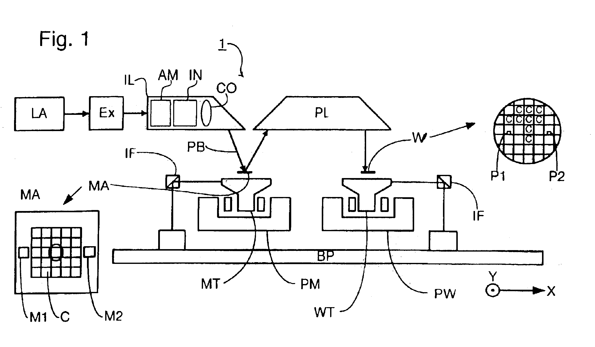
[0038]FIG. 1 schematically depicts a lithographic projection apparatus 1 according to an embodiment of the invention. The apparatus 1 includes a base plate BP; a radiation system, Ex, IL constructed and arranged to supply a projection beam PB of radiation (e.g. EUV radiation), which in this particular case also comprises a radiation source LA; a first object (mask) table MT provided with a mask holder constructed and arranged to hold a mask MA (e.g. a reticle), and connected to a first positioning device PM that accurately positions the mask with respect to a projection system or lens PL; a second object (substrate) table WT provided with a substrate holder constructed and arranged to hold a substrate W (e.g. a resist-coated silicon wafer), and connected to a second positioning device PW that accurately positions the substrate with respect to the projection system PL. The projection system or lens PL (e.g. a mirror group) is constructed and arranged to image an irradiated portion of...


PUM


Abstract

A reflective mask has a sub-resolution texture applied to absorbing areas to reduce the amount of power in the specular reflection. The texture may form a phase contrast grating or may be a diffuser. The same technique may be applied to the other absorbers in a lithographic apparatus.

Description

RELATED APPLICATION[0001]This application claims the benefit of priority to European Patent Application No. 02251652.0, filed Mar. 8, 2002, the entire contents of which are herein incorporated by reference.BACKGROUND OF THE INVENTION[0002]1. Field of the Invention[0003]The present invention relates to a mask for use in lithography, a method of making a mask, a lithographic apparatus and a device manufacturing method.[0004]2. Description of the Related Art[0005]The term “patterning device” as here employed should be broadly interpreted as referring to device that can be used to endow an incoming radiation beam with a patterned cross-section, corresponding to a pattern that is to be created in a target portion of the substrate. The term “light valve” can also be used in this context. Generally, the pattern will correspond to a particular functional layer in a device being created in the target portion, such as an integrated circuit or other device (see below). An example of such a pat...

Claims


Application Information

Patent Timeline
IPC IPC(8): G03F7/20G03F1/14G03F1/00G03F1/24H01L21/027
CPCB82Y10/00B82Y40/00G03F1/144G03F1/24G03F7/70283G03F1/50G03F1/52
Inventor EURLINGS, MARKUS FRANCISCUS ANTONIUSVAN DIJSSELDONK, ANTONIUS JOHANNES JOSEPHUSDIERICHS, MARCEL MATHIJS THEODORE MARIE
Owner ASML NETHERLANDS BV
Why Eureka
Try Eureka