Circuit breaker
a circuit breaker and circuit technology, applied in the field of circuit breaker, can solve the problems of large friction loss, actuated circuit breaker, high sealing requirements at the shaft bushing, etc., and achieve the effects of reducing or eliminating power loss, reducing leakage risk, and reducing the size of motors and converters
Inactive Publication Date: 2005-08-09
ABB (SCHWEIZ) AG
View PDF6 Cites 20 Cited by
- Summary
- Abstract
- Description
- Claims
- Application Information
AI Technical Summary
Benefits of technology
[0009]Against this background the object of the invention is to reduce the power losses in a circuit breaker driven by an electric motor and to achieve greater security against gas leakage when solving the above-mentioned problems.
[0011]Thanks to the entire motor being arranged in the same gas-tight housing that surrounds the contacts, the problem described above concerning sealing around the shaft that transmits the motor movement to the movable contact, and the risk of leakage, are eliminated. The only bushing that must be hermetically sealed is the electric cable supplying current to the motor. Since this does not move the seal is completely problem free and causes no power loss. The circuit breaker in accordance with the invention thus enables the power loss to be reduced or eliminated and the motor and converter to be made smaller. The above-mentioned problems related to previously known technology are thus solved.
Problems solved by technology
However, a spring-actuated circuit breaker has a number of drawbacks.
This places great demands on the sealing at the shaft bushing.
This entails considerable friction losses.
The cost of these thus also increases.
This reduces the possibility of using standard components for the circuit breaker and its peripherals.
Another drawback with the motor described in DE 3224165 is that a wall exists between stator and rotor.
The gap will therefore be large, thus considerably reducing the efficiency of the motor.
Method used
View moreImage
Smart ImageViewing Examples

Examples
first embodiment
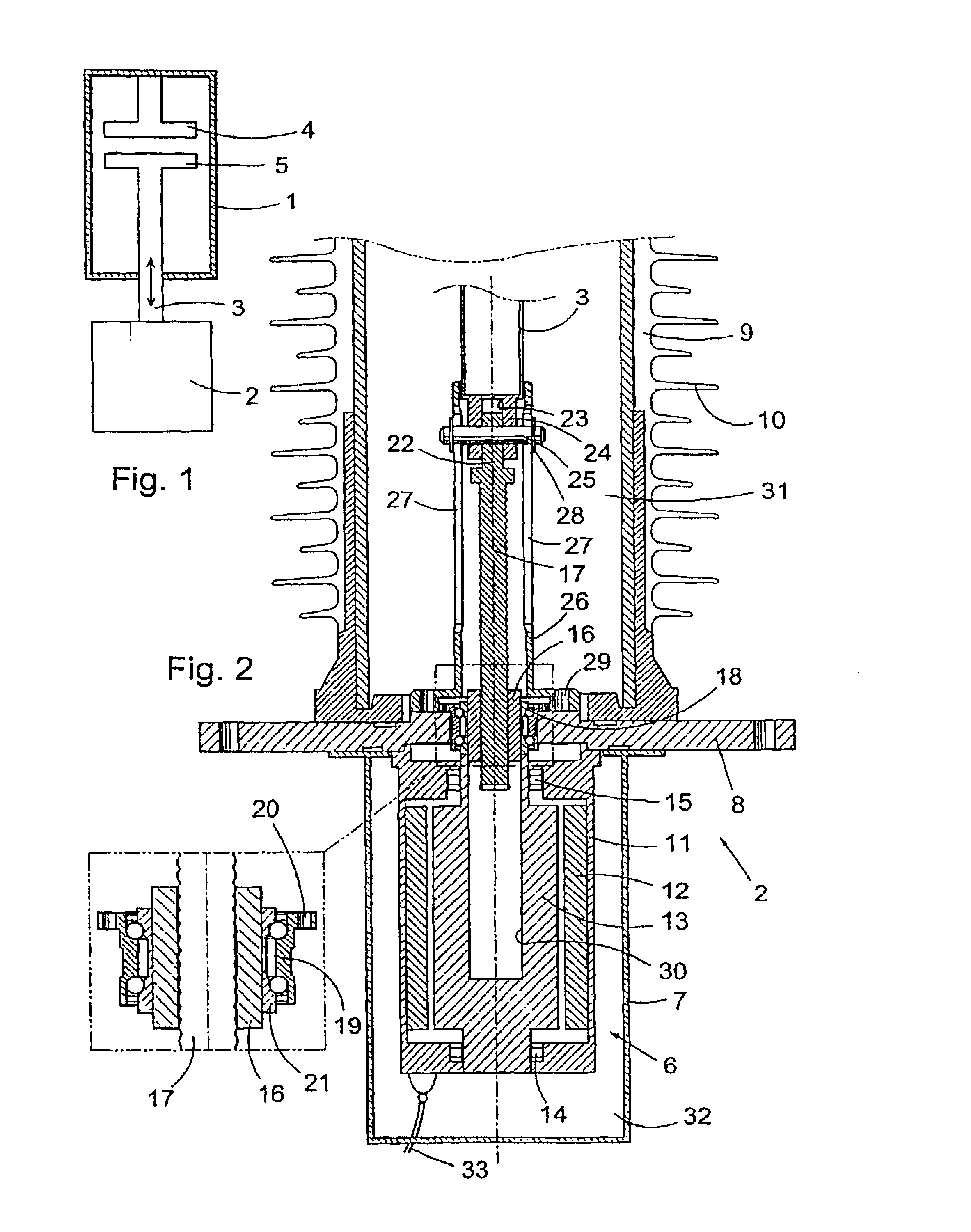
[0021]FIG. 2 is a longitudinal section through the actuating means and motor for a circuit breaker in accordance with the invention.
second embodiment
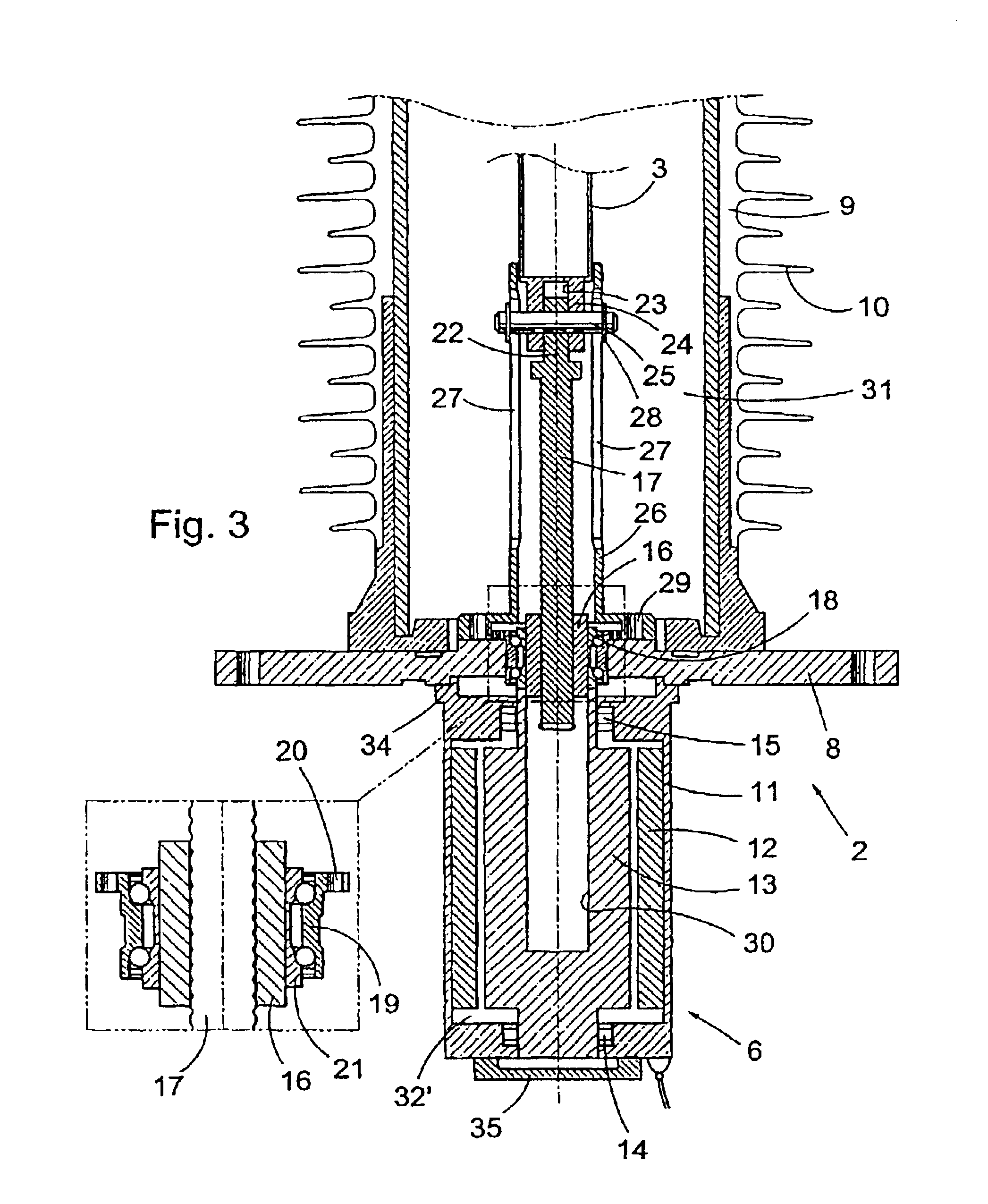
[0022]FIG. 3 is a longitudinal section through the actuating means and motor for a circuit breaker in accordance with the invention.
third embodiment
[0023]FIG. 4 is a longitudinal section through the actuating means and motor for a circuit breaker in accordance with the invention.
[0024]FIG. 5 illustrates an embodiment of the invention as applied to a three-pole circuit breaker.
[0025]FIG. 6 is a diagram showing a part of a switchgear station in accordance with the invention.
Login to View More PUM
 Abstract
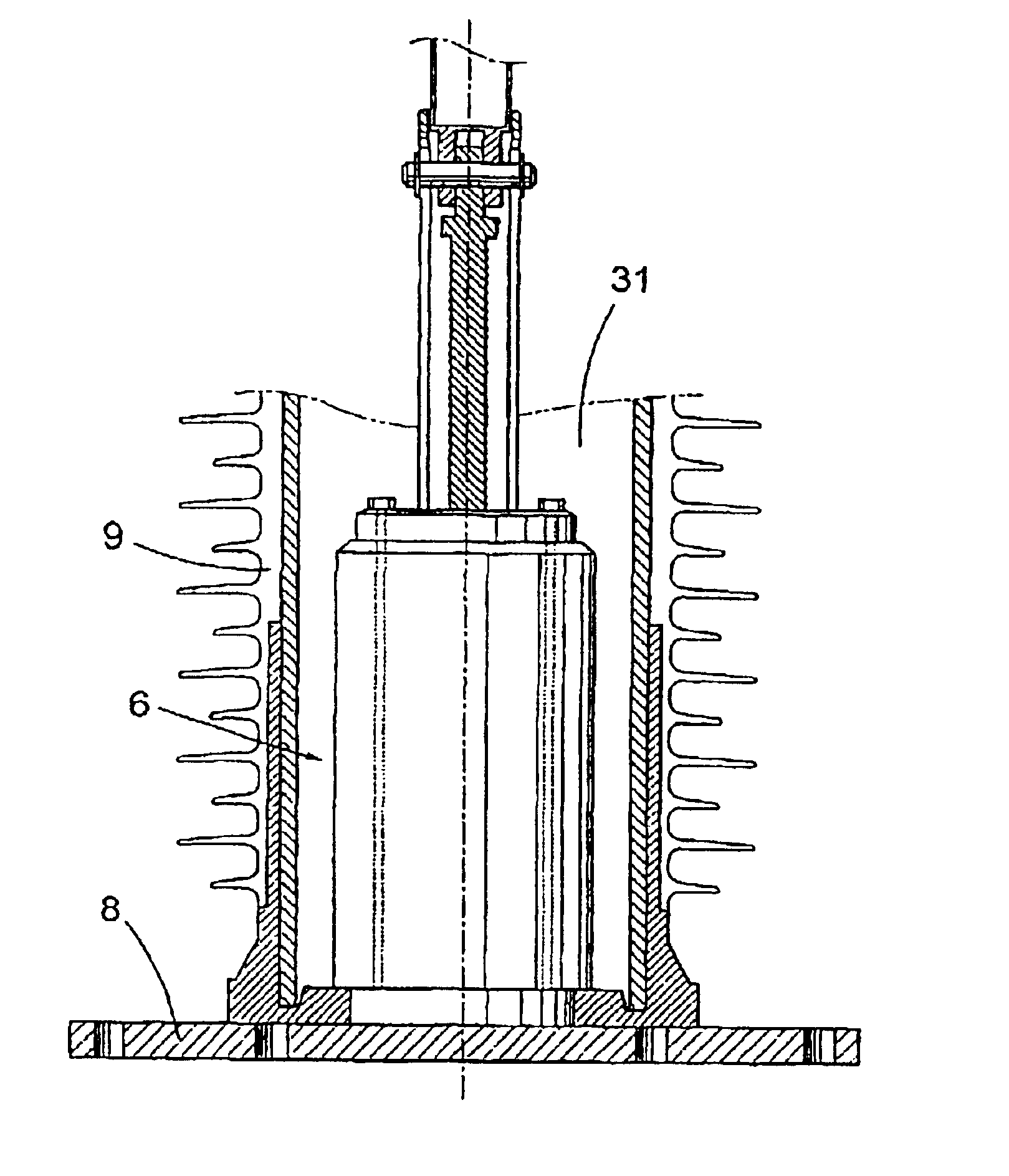
The invention relates to a circuit breaker, preferably for high or medium voltage. The movable conact of each breaker pole is connected, via mechanical means for transmitting movement, to a movable part of an electric motor (6). The movable contact and the means for transmitting movement are arranged in a gas-tight apparatus chamber (31) surrounded by a gas-tight apparatus housing (9) of insulating material such as porcelain. In accordance with the invention the motor (6) is arranged entirely in the apparatus chamber (31). The invention also relates to an electric plant provided with the breaker claimed, uses of the breaker claimed and a method of breaking electric current in which the breaker claimed is used.
Description
TECHNICAL FIELD[0001]The present invention relates in a first aspect to a circuit breaker of the type described in the preamble to claim 1. The breaker is thus actuated by an electric motor. In second, third, fourth and fifth aspects the invention relates to an electric plant provided with such a circuit breaker, to the use of such a circuit breaker, to a method of disconnecting an electric current and to a method of manufacturing a circuit breaker, respectively.[0002]Circuit breakers of this type are used in electric plants such as switchgear stations in order to disconnect the current when necessary. A circuit breaker shall be able to disconnect and connect normal load currents but, most importantly, it must be able to very rapidly break the short-circuiting currents that arise in the event of a fault in the system. The main components of a circuit breaker are breaker chamber and actuating means. Disconnection and connection of the current is effected by contacts in the breaker ch...
Claims
Login to View More Application Information
Patent Timeline
 IPC IPC(8): H01H33/28H01H33/36H01H33/02H01H33/56
CPCH01H33/36H01H33/022H01H33/56H01H2003/268
Inventor THURESSON, PER OLOFHERMANSSON, LARSROININEN, TOMASVALDERMARSSON, STEFAN
Owner ABB (SCHWEIZ) AG