
Orientation division type liquid crystal display, fabrication method thereof and image display method

a technology of liquid crystal display and orientation division, which is applied in the direction of identification means, instruments, non-linear optics, etc., can solve the problems of difficult to control the initial orientation of liquid crystal molecules to a desired angle, difficult to shorten the response time, and difficult to form a clearly defined step portion. , to achieve the effect of widening the viewing field of pixel display, reducing initial orientation response time, and clarifying the pixel display

Inactive Publication Date: 2005-08-09
GOLD CHARM LTD
View PDF14 Cites 11 Cited by
  • Summary
  • Abstract
  • Description
  • Claims
  • Application Information

AI Technical Summary

Benefits of technology

[0020]An object of the present invention is to provide, in a liquid crystal display device including a substrate having a COT structure in which pixel color layers as color filters and pixel electrodes are provided on the substrate and various electrodes or electrode wiring are concentrically provided in peripheries of the pixel color layers, an orientation division type liquid crystal display device, which is superior in response time for initial orientation, capable of clearly and evenly dividing the orientation direction to a plurality of directions to thereby widen a viewing angle of pixel display.

Problems solved by technology

However, since the orientation control dislocation layer is usually formed by etching SiNx or SiO2, etc., it is not easy to form a clearly defined step portion.
Furthermore, it is very difficult to control the initial orientation of liquid crystal molecules to a desired angle by such gentle slope formed on suchsmall step portion.
Therefore, it is very difficult to shorten the response time by more clearly dividing the initial orientation direction.

Method used


Image

  • Orientation division type liquid crystal display, fabrication method thereof and image display method
  • Orientation division type liquid crystal display, fabrication method thereof and image display method
  • Orientation division type liquid crystal display, fabrication method thereof and image display method

Examples


embodiment 1

(Embodiment 1)

[0097]Four liquid crystal cells having the COT structures including step portions having slope length L of 2.0 μm commonly and heights H of 0.4 μm, 0.8 μm, 1.1 μm and 1.8 μm, respectively, were prepared and response times of the respective liquid crystal cells were measured while applying voltages in a range from 0 V to 5 V across the liquid crystal cells. Table 1 and FIG. 8A show the result of the measurement. Incidentally, the thickness of the liquid crystal layers, that is, the second cell gaps G2, were 4.0 μm, commonly.

[0098]

TABLE 1slope height (μm)no slope0.40.81.21.8height ratio (%)—10202845response time (ins)272.962.131.920.615.7

[0099]The height ratio in Table 1 is a ratio (%) of the height of the slope to the thickness of the liquid crystal layer.

[0100]As is clear from Table 1, the response time is substantially improved by the provision of the slope formed on the step portion. When the slope height is 0.8 μm, the response time becomes about a half of that obta...

embodiment 2

(Embodiment 2)

[0105]Four liquid crystal cells having the COT structures, 15 which are similar to those in the embodiment 1 and include step portions having slope heights H of 1.1 μm commonly and slope lengths L of 1.2 μm, 2.0 μm, 3.5 μm and 5.8 μm, respectively, were prepared and response times of the respective liquid crystal cells were measured while applying voltages in a similar range to that used in the embodiment 1 across the liquid crystal cells. Table 2 and FIG. 8B show the result of the measurement. Incidentally, the thickness' of the liquid crystal layers, that is, the second cell gaps G2, were 4.0 μm, commonly, and the tilting angle θ of the slope is represented by the following equation:

θ=tan−1(H / L)

[0106]

TABLE 2slope length (μm)no slope1.22.03.55.8tilting angle (θ)—43291711response time (ms)272.918.120.631.048.2

[0107]As is clear from Table 2, the response time to the orientation division of the liquid crystal layer is substantially improved by the provision of the slope ...


PUM

PropertyMeasurementUnit
thicknessaaaaaaaaaa
thicknessaaaaaaaaaa
lengthaaaaaaaaaa

Abstract

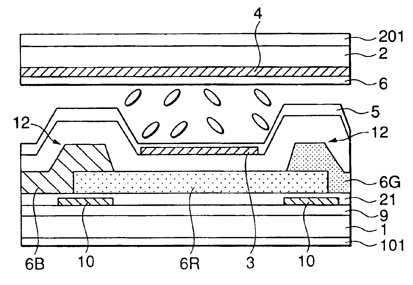
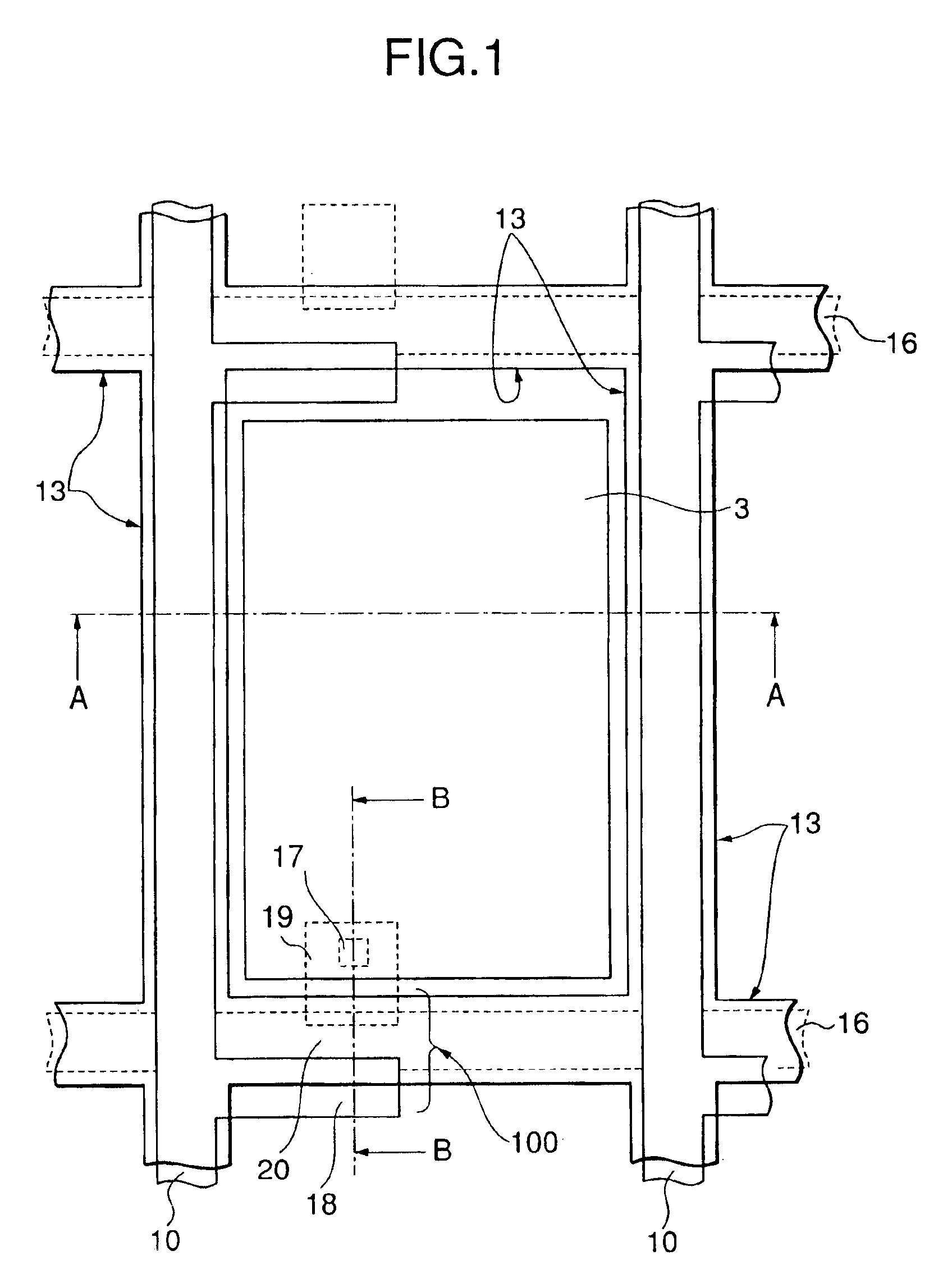
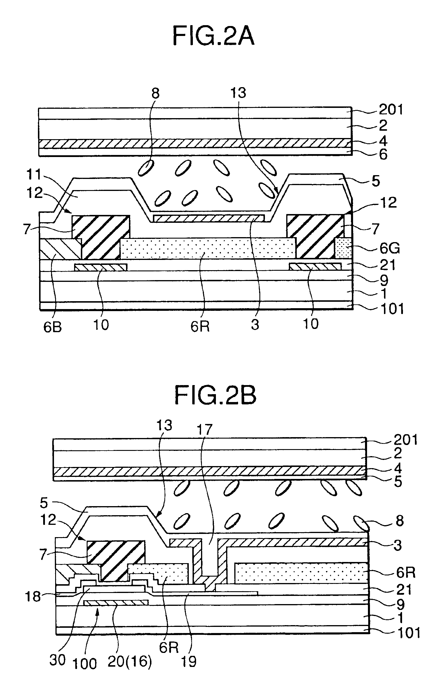
In an orientation division type liquid crystal display device for widen a viewing angle of a display pixel of an active matrix type liquid crystal color display device having a COT structure, pixel color layers (6B, 6R, 6G) as color filters and pixel electrodes 3 are formed on a substrate on the side of the pixel electrodes and slopes 13 are provided along four side peripheries of each pixel electrode. Liquid crystal molecules 8 between each pixel electrode of the pixel electrode substrate and a common electrode of an opposing substrate are controlled in orientation direction along the slopes to divide it to a plurality of directions to thereby widen a viewing angle of a pixel display. The slope is formed on a step portion 12 formed by a BM layer formed on at least one of a gate electrode, a drain electrode and a source electrode formed in a periphery of the pixel electrode or at least one of a gate wiring and a drain wiring formed in the periphery or a step portion formed by partially overlapping peripheral portions of the adjacent pixel color layers.

Description

CROSS-REFERENCE TO RELATED APPLICATIONS[0001]The present application is a divisional of application Ser. No. 09 / 741,330 filed on Dec. 20, 2000 now U.S. Pat. No. 6,768,530.BACKGROUND OF THE INVENTION[0002]1. Field of the Invention[0003]The present invention relates to an orientation division type liquid crystal display device and a fabrication method thereof and, particularly, the present invention relates to an orientation division type liquid crystal display device of an active matrix drive type, which has a COT (Color filter on TFT) structure in which color filters are arranged on a pixel electrode side substrate having TFT (Thin Film Transistor) switching elements, which is capable of widening a viewing angle of pixel display. Furthermore, the present invention relates to an image display method for use in the orientation division type liquid crystal display device to widen a viewing angle of the pixel display.[0004]2. Description of the Prior Art[0005]The liquid crystal display ...

Claims


Application Information

Patent Timeline
Patent Type & Authority Patents(United States)
IPC IPC(8): G02F1/13G02F1/139G02F1/1335G02F1/1333G02F1/1337G02F1/1343G02F1/136G09F9/30
CPCG02F1/1393G02F1/133512G02F1/133707G02F1/136
Inventor MATSUYAMA, HIROAKIKAWADA, KIYOMISUZUKI, SEIJIHIRAI, YOSHIHIKOSAKAMOTO, MICHIAKIOKAMOTO, MAMORUYAMAMOTO, YUJIISHII, TOSHIYASUZUKI, TERUAKISUMIYOSHI, KENSUZUKI, MASAYOSHI
Owner GOLD CHARM LTD
Learn More