Guard ring for direct photo-to-electron conversion detector array

a detector array and photo-to-electron technology, applied in the direction of instruments, radiation controlled devices, optical radiation measurement, etc., can solve the problems of significant non-uniformity or visible artifacts, high undesirable artifacts around the edges of tiles, and the lik

Inactive Publication Date: 2005-08-09
GE MEDICAL SYST GLOBAL TECH CO LLC
View PDF14 Cites 28 Cited by
  • Summary
  • Abstract
  • Description
  • Claims
  • Application Information

AI Technical Summary

Problems solved by technology

For tiled imaging detectors built with room temperature semiconductors, the edges of each tile can cause significant non-uniformity or visible artifacts.
This is known to arise due to the much higher leakage current and distorted electric field near the edges.
Artifacts around the edges of the tiles may be highly undesirable.
These artifacts are believed to be caused by the degraded performance of the edge pixels.
These artifacts become roadblocks for the implementation of these detectors and detector arrays in medical imaging applications where line artifacts are prohibited.
This is undesirably for tiled detector boundaries or detector edges which can have a very limited tolerance to inactive space.
Thus existing guard ring designs may also be unsuitable for medical imaging applications wherein line artifacts due to the inactive space may be unacceptable.

Method used


Image

  • Guard ring for direct photo-to-electron conversion detector array
  • Guard ring for direct photo-to-electron conversion detector array
  • Guard ring for direct photo-to-electron conversion detector array

Examples


Embodiment Construction

)

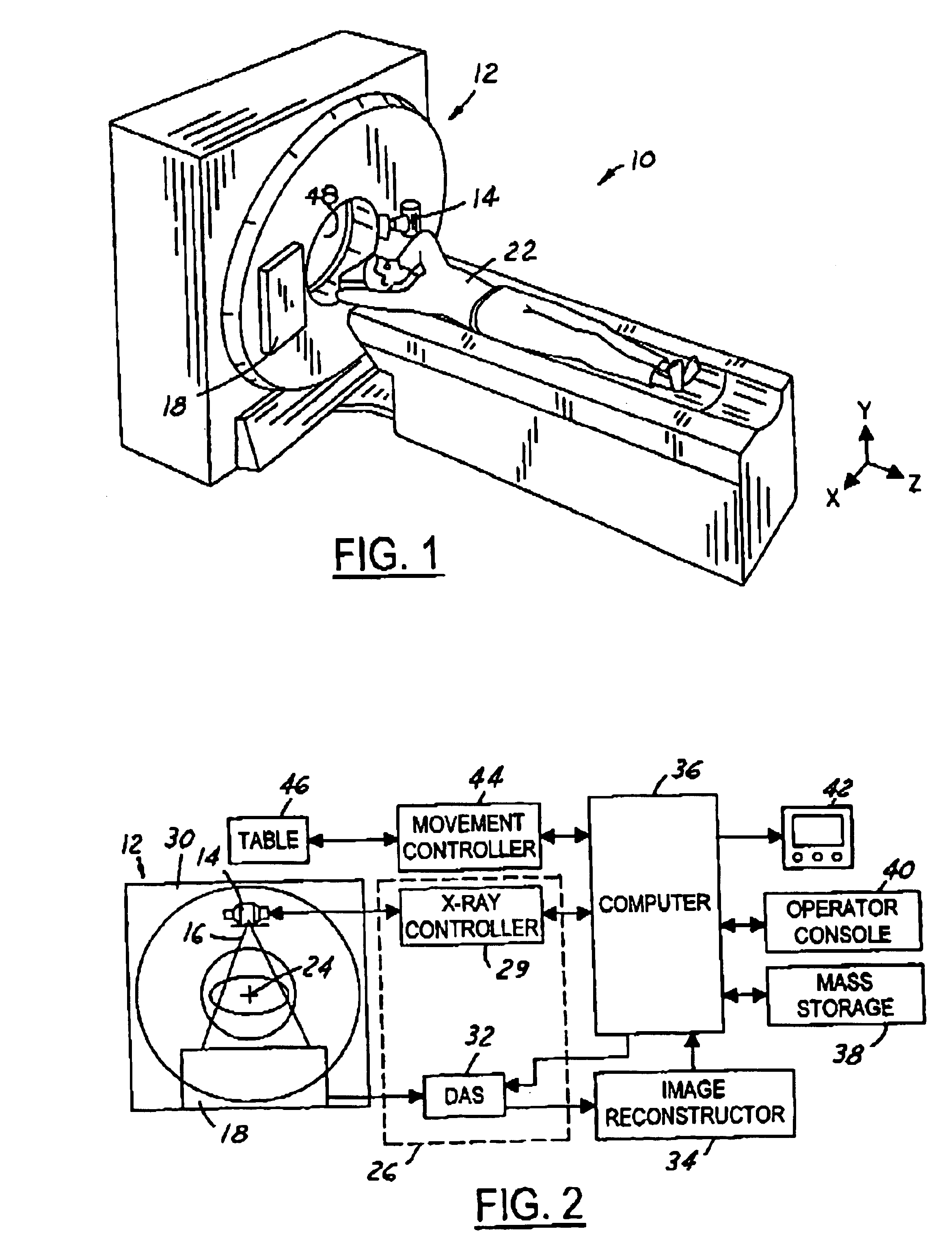
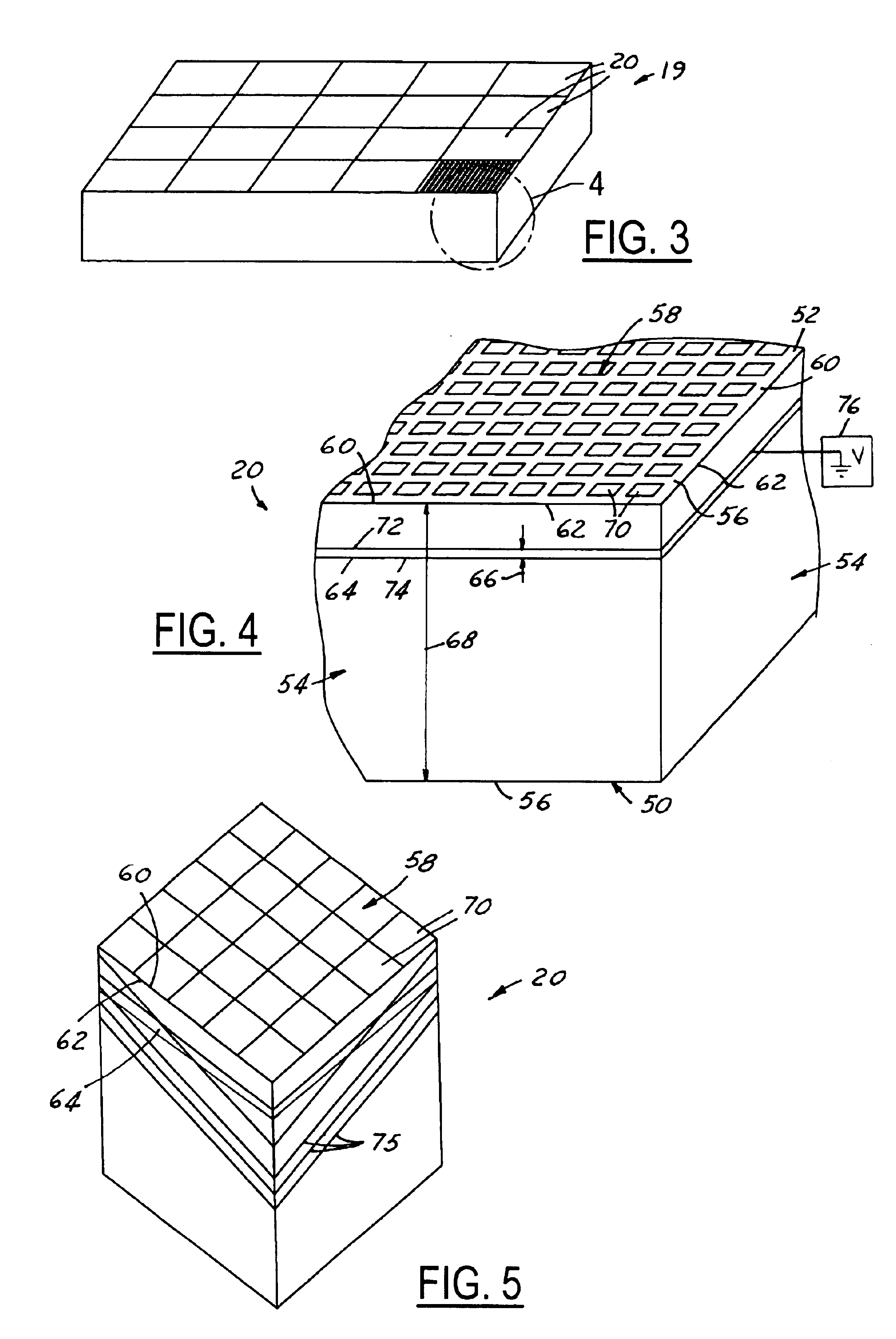
[0015]Referring now to FIG. 1, which is an illustration of a computed tomography (CT) imaging system 10 for use with the detector assembly 18 of the present invention. Although a particular CT imaging system 10 has been illustrated, it should be understood that the detector assembly 18 of the present invention can be utilized in a wide variety of imaging systems. The CT imaging system 10 includes a scanner assembly 12 illustrated as a gantry assembly. The scanner assembly 12 includes an x-ray source 14 for projecting a beam of x-rays 16 toward a detector assembly 18 positioned opposite the x-ray source 14. The detector assembly 18 includes a direct conversion detector array 19 comprised of a plurality of direct conversion detector elements 20 (see FIG. 3) which combine to sense the projected x-ray photons 16 that pass through an object, such as a medical patient 22. Each of the plurality of direct conversion detector elements 20 produces an electrical signal that represents the int...


PUM

PropertyMeasurementUnit
electric potential distributionaaaaaaaaaa
heightaaaaaaaaaa
heightaaaaaaaaaa

Abstract

A device for use in an imaging system is provided including a direct conversion detector element configured to convert x-ray photons into electric current. The direct conversion detector element is comprised of a cathode surface, an anode surface having a plurality of anode side edges, and a plurality of detector side surfaces connecting the cathode surface to the anode surface. The plurality of detector side surfaces each have a detector depth. The device further includes a pixel array assembly positioned on the anode surface. The pixel array assembly includes a plurality of pixel side edges. Each of the plurality of pixel side edges is immediately adjacent one of the anode side edges. A guard ring is mounted around the plurality of detector side surfaces. The guard ring includes an upper ring edge, a lower ring edge, and a ring outer surface including a guard ring height.

Description

TECHNICAL FIELD[0001]The present invention relates generally to detector elements for use in medical imaging, and more particularly, to direct conversion detector arrays for use in medical imaging.BACKGROUND OF THE INVENTION[0002]Direct conversion detectors and detector arrays are utilized in medical imaging in order to convert x-ray photons directly into electric charges. They are typically comprised of an x-ray photoconductor layer grown directly on top of the charge collector and readout layer (such as room temperature semi-conductors). The detectors are commonly utilized in arrays of multiple detector (or tiles) such that an increased image size with improved resolution may be generated.[0003]The performance of the detectors, especially the peripheral detector elements, can be important to many imaging applications. The linearity, uniformity, stability, and consistency can be especially important for peripheral detectors. For many applications, such as mammography chest wall dea...

Claims


Application Information

Patent Timeline
Patent Type & Authority Patents(United States)
IPC IPC(8): A61B6/03A61B6/00G01J1/00G01N23/00G01T1/24G01T1/29G21K1/12H01L25/00H01L27/00H01L27/14H01L27/146H01L31/00H01L31/04H01L31/09H04N5/32H05G1/60H05G1/64
CPCA61B6/032G01T1/241H01L27/14603H01L27/14659
Inventor LI, WENZHAO, JIANGUO
Owner GE MEDICAL SYST GLOBAL TECH CO LLC
Why Eureka
Try Eureka