
Method and apparatus for packaging optical fiber sensors for harsh environments

a technology of optical fiber and packaging method, applied in the field of optical fiber sensors, can solve the problem that the sensor package must have a small size, and achieve the effect of reducing the amount of air trapped inside the packag

Inactive Publication Date: 2005-08-09
VIRGINIA TECH INTPROP INC
View PDF3 Cites 31 Cited by
  • Summary
  • Abstract
  • Description
  • Claims
  • Application Information

AI Technical Summary

Benefits of technology

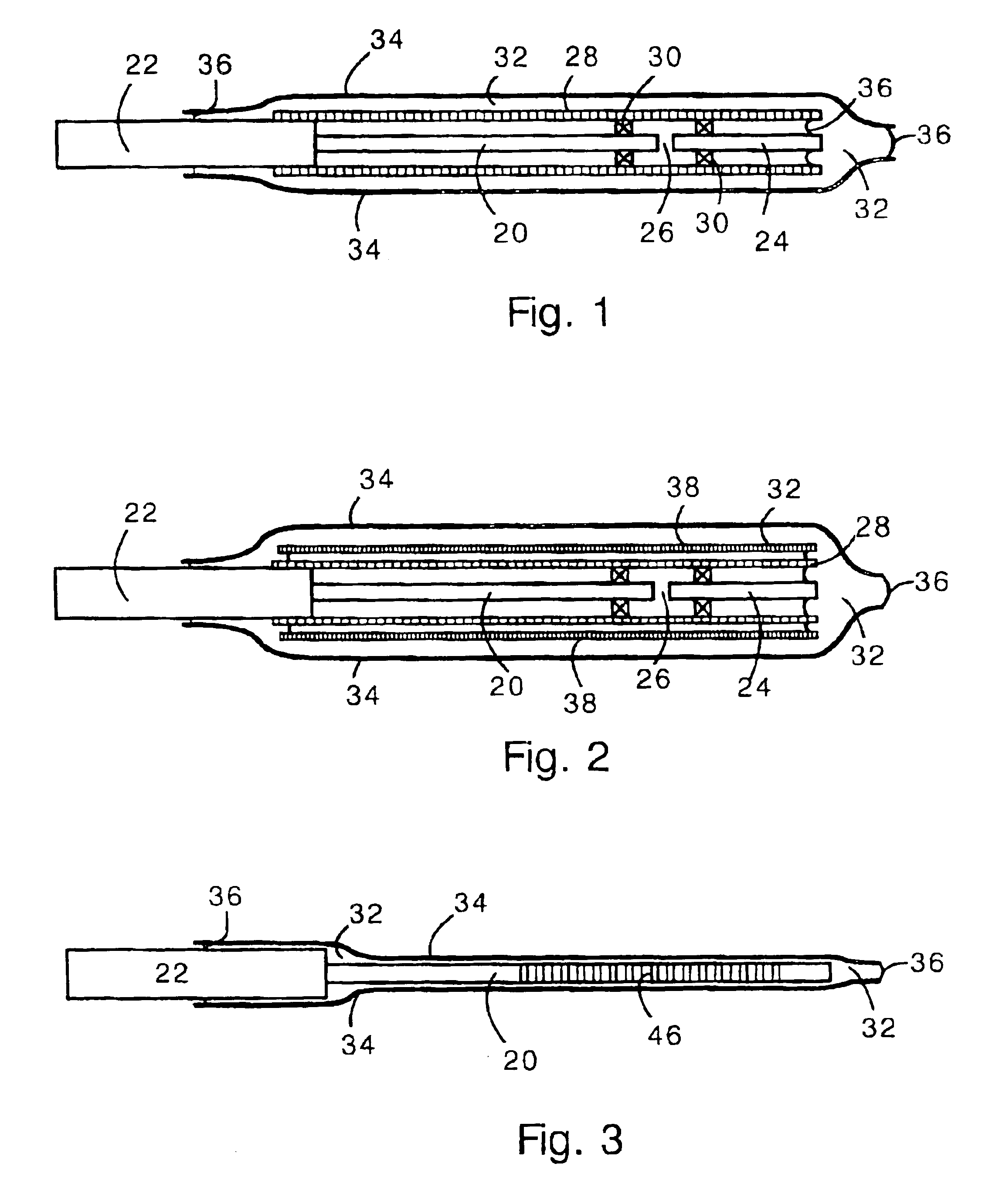
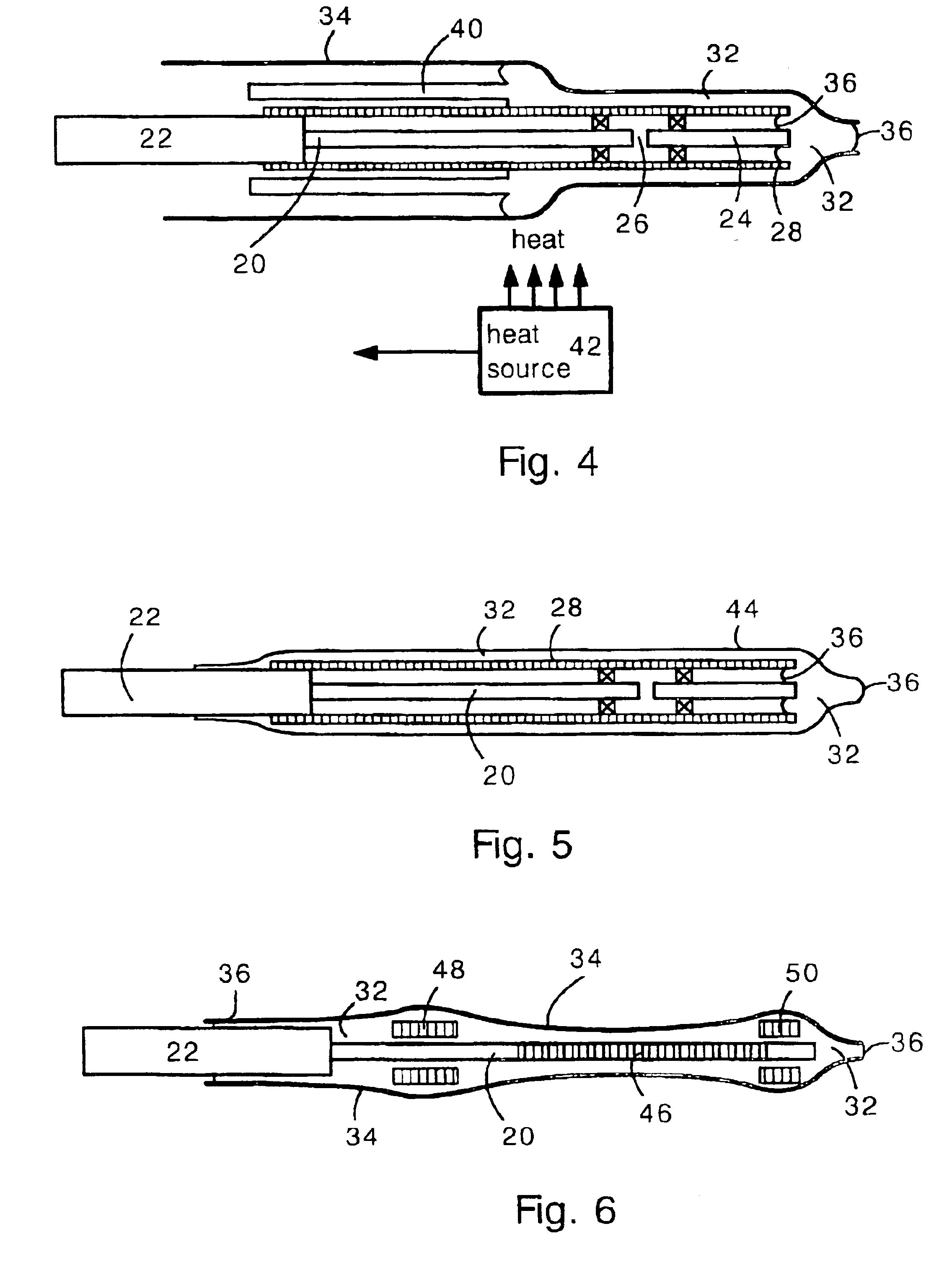
[0012]The present invention includes a method for making the present sensor package. The present sensor package is made by disposing the sensor and the low melting point metal into the heat shrink tube and heating the tube and metal so that the metal melts and the tube shrinks. This causes the tube to press the metal against the sensor. The location of applied heat can be scanned across the sensor to minimize the amount of air trapped within the package.

Problems solved by technology

The downhole environment is a challenging place to locate an optical fiber sensor because of mechanical shock, chemical corrosion, thermal degradation, and water penetration that can occur.
Additionally, the sensor package must have a small size because space is limited in the downhole environment.

Method used


Image

  • Method and apparatus for packaging optical fiber sensors for harsh environments
  • Method and apparatus for packaging optical fiber sensors for harsh environments
  • Method and apparatus for packaging optical fiber sensors for harsh environments

Examples


Embodiment Construction

[0020]The present invention provides a fiber optic sensor package that is inexpensive and suitable for use in harsh environments such as a downhole environment (e.g. oil well). The present package provides exceptional mechanical and chemical protection, and is compatible for use at high pressure. Also, the present package is simple and inexpensive to fabricate, and can be used with a wide range of fiber optic sensors.

[0021]The present fiber sensor package has a optical fiber sensor within a metal jacket made of low melting point metal (e.g. lead, tin, indium or their alloys) surrounded by a shrunken heat shrink tubing. The heat shrink tubing is shrunken while the low melting point metal is in a molten state, thereby squeezing out excess metal (if any). The low melting point metal jacket provides an inexpensive and durable coating that, in combination with the heat shrink tubing provides mechanical and chemical protection. Preferably, the metal has a melting point equal to or lower t...


PUM


Abstract

A package for an optical fiber sensor having a metal jacket surrounding the sensor, and heat-shrink tubing surrounding the metal jacket. The metal jacket is made of a low melting point metal (e.g. lead, tin). The sensor can be disposed in a rigid tube (e.g. stainless steel or glass) that is surrounded by the metal jacket. The metal jacket provides a hermetic, or nearly hermetic seal for the sensor. The package is made by melting the metal jacket and heating the heat shrink tubing at the same time. As the heat-shrink tubing shrinks, it presses the low melting point metal against the sensor, and squeezes out the excess metal.

Description

CROSS-REFERENCE TO RELATED APPLICATIONS[0001]This application claims priority to U.S. Provisional Patent Application 60 / 419,535 filed on Oct. 21, 2002, the complete contents of which are herein incorporated by reference.STATEMENT OF GOVERNMENT INTEREST[0002]This invention was made with government support under Contract Number DE-FT26-98BC15167 awarded by the U.S. Department of Energy. The Government has certain rights in the invention.FIELD OF THE INVENTION[0003]The present invention relates generally to optical fiber sensors. More particularly, the present invention provides a method and apparatus for packaging optical fiber sensors which may be used in an oil well downhole, or in other harsh environments. The package employs a low melting point metal jacket inside heat shrink tubing.BACKGROUND OF THE INVENTION[0004]Optical fiber sensors are employed for measuring temperature, pressure or other physical parameters. Optical fiber sensors are sometimes employed in extreme environment...

Claims


Application Information

Patent Timeline
IPC IPC(8): G02B6/02
CPCG02B6/02209
Inventor PICKRELL, GARYDUAN, YUHONGWANG, ANBO
Owner VIRGINIA TECH INTPROP INC
Learn More