
Apparatus and methods for ferroelectric ram fatigue testing

Active Publication Date: 2005-08-09
TEXAS INSTR INC
View PDF6 Cites 7 Cited by
  • Summary
  • Abstract
  • Description
  • Claims
  • Application Information

AI Technical Summary

Benefits of technology

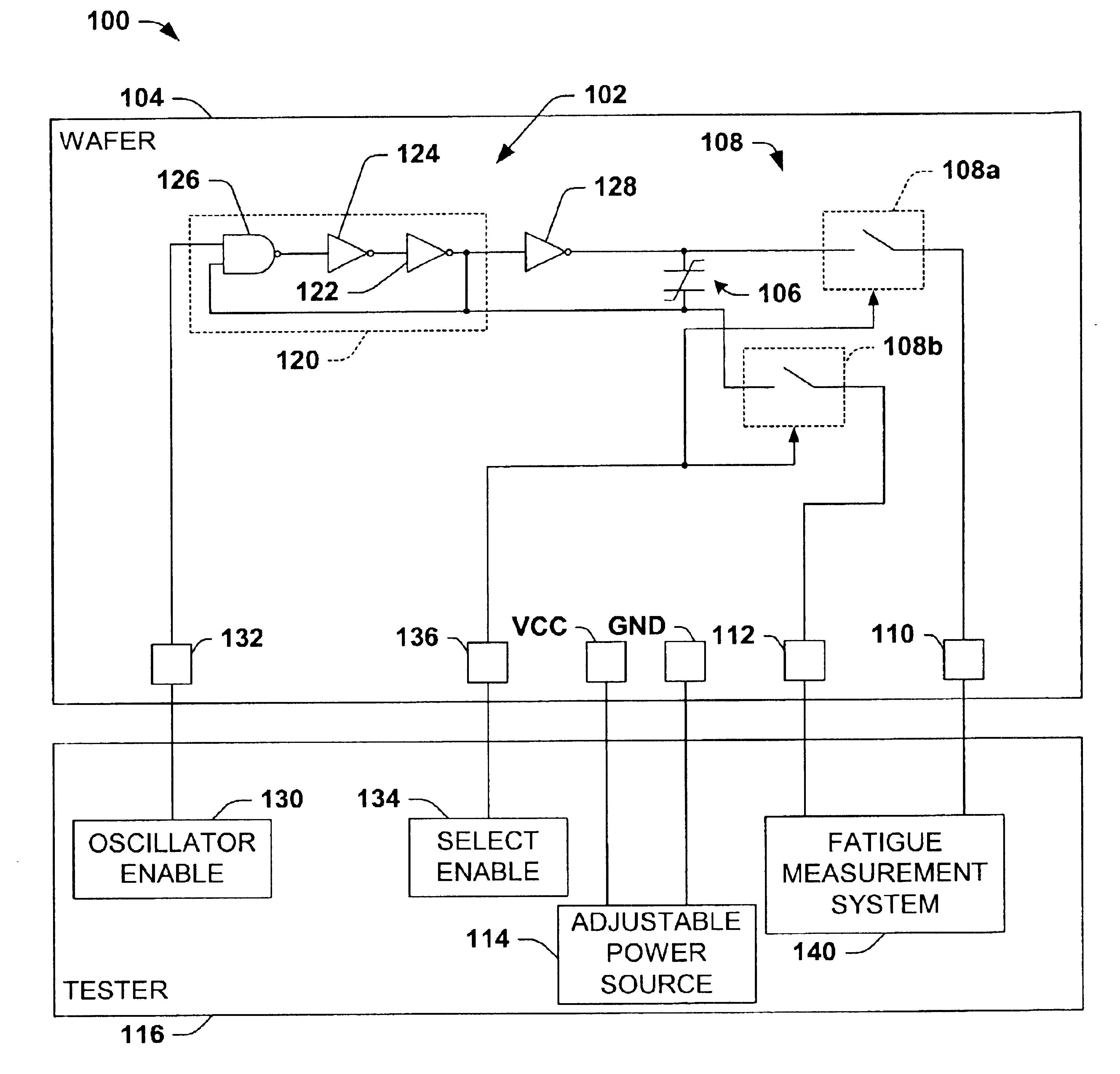
[0011]The apparatus comprises an oscillator fabricated in the wafer, which selectively provides a bipolar waveform to a ferroelectric capacitor in the wafer, as well as a switching system fabricated in the wafer, which operates to selectively provide access to first and second electrodes of the ferroelectric capacitor. In one example, the oscillator comprises a ring oscillator circuit providing an output waveform to one electrode of the ferroelectric capacitor, and an inverter receiving the output waveform from the ring oscillator circuit and providing an inverted output waveform to the other ferroelectric capacitor electrode. The on-chip oscillator is operable to provide the bipolar waveform having a frequency of about 1 GHz or more to the ferroelectric capacitor. This allows improved test throughput, by which testing of 1E14 cycles (e.g., or other desired number of cycles) may be completed in much less time than was possible using conventional test setups. The switching system may comprise one or more switching devices, such as “T-gate” or“T-switch” circuits.
[0013]The invention also provides thermal acceleration to further expedite fatigue testing. In one example, the apparatus comprises a resistor fabricated in the wafer proximate the ferroelectric capacitor, which is operable to raise the temperature of the ferroelectric capacitor when a current is passed therethrough. The resistor may comprise a polysilicon resistor structure fabricated in the wafer proximate the ferroelectric capacitor. The voltage acceleration features and the thermal acceleration features of the invention may be provided separately or in combination with the frequency acceleration advantages of the on-chip oscillator to facilitate faster ferroelectric fatigue testing than was possible using conventional setups, wherein testing that previously took thousands of hours may be completed in one or a few hours in certain implementations. Thus, the invention facilitates evaluation of ferroelectric memory products in near real-time, finding utility in manufacturing applications to determine whether fabrication process parameters need adjustment.

Problems solved by technology

The data is then restored to the ferroelectric cell capacitor, as the read operation is destructive.
Since the read operation in a ferroelectric memory is destructive, this means that ferroelectric memory devices must withstand a certain number of read / restore operations, with little or no performance degradation.
This life cycling is generally limited to application of pulse waveforms of frequencies in the range of about 1 MHz or less, due to the capacitive loading effects of the external probes.
However, this frequency limitation of conventional fatigue testing setups causes the test to extend for an unacceptably long time.
This limitation renders conventional test setups and methodologies unfit for in-line testing of ferroelectric memory devices in a production setting.
However, process personnel cannot wait for hundreds or thousands of hours to obtain this type of information.

Method used


Image

  • Apparatus and methods for ferroelectric ram fatigue testing
  • Apparatus and methods for ferroelectric ram fatigue testing
  • Apparatus and methods for ferroelectric ram fatigue testing

Examples


Embodiment Construction

[0033]The present invention will now be described with reference to the attached drawings, wherein like reference numerals are used to refer to like elements throughout. The invention relates to test apparatus and systems, as well as methods for fatigue testing ferroelectric material in a wafer. Various aspects of the invention are hereinafter illustrated and described in the context of ascertaining the onset and extent of fatigue in ferroelectric capacitors fabricated in a wafer, wherein the ferroelectric capacitor under test may be one or more dedicated test capacitors and / or one or more core memory cell ferroelectric capacitors. However, it will be appreciated that the invention is not limited to the illustrated implementations, and that the various aspects of the invention may be implemented alone or in combination in association with other semiconductor devices having ferroelectric materials formed therein.

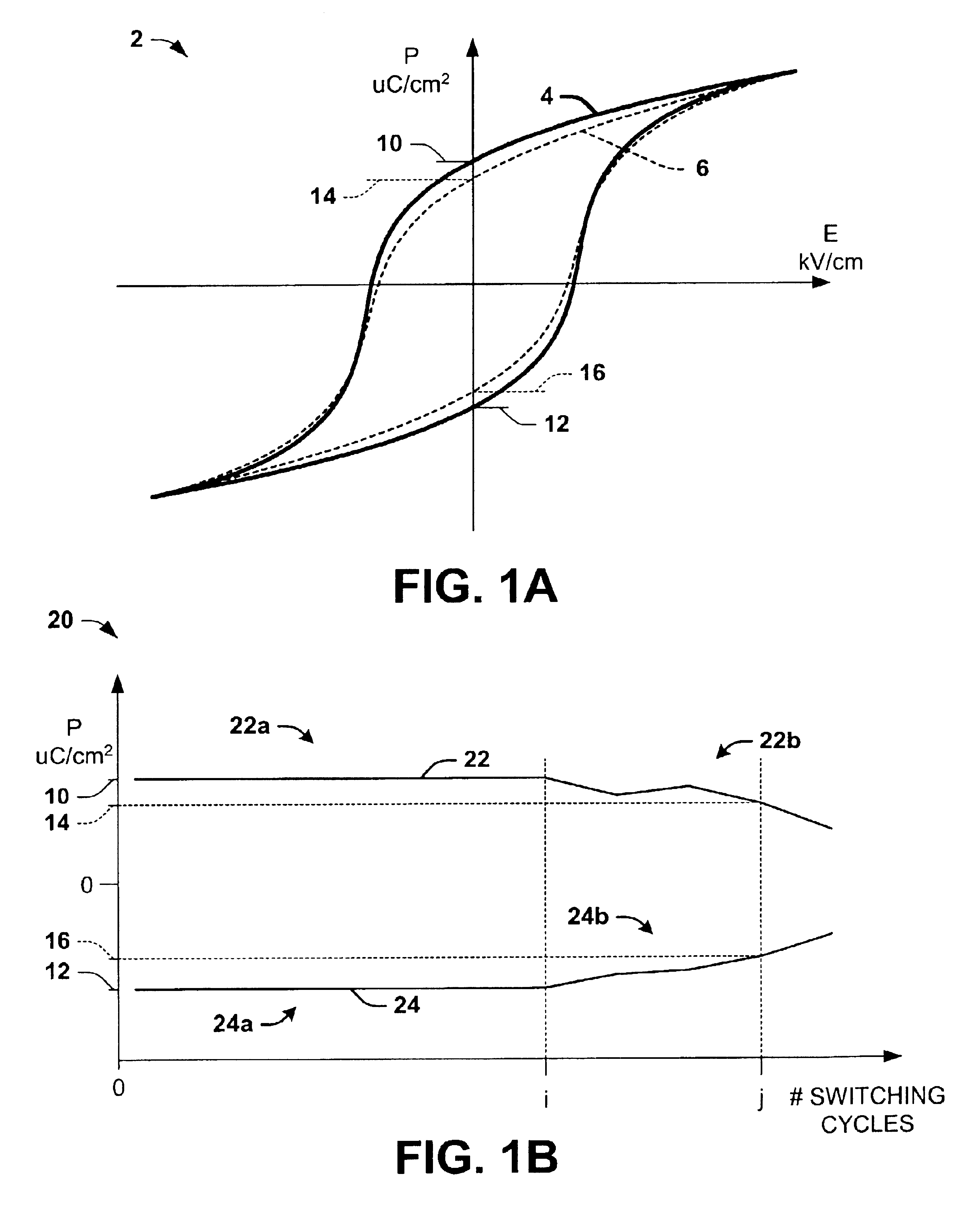
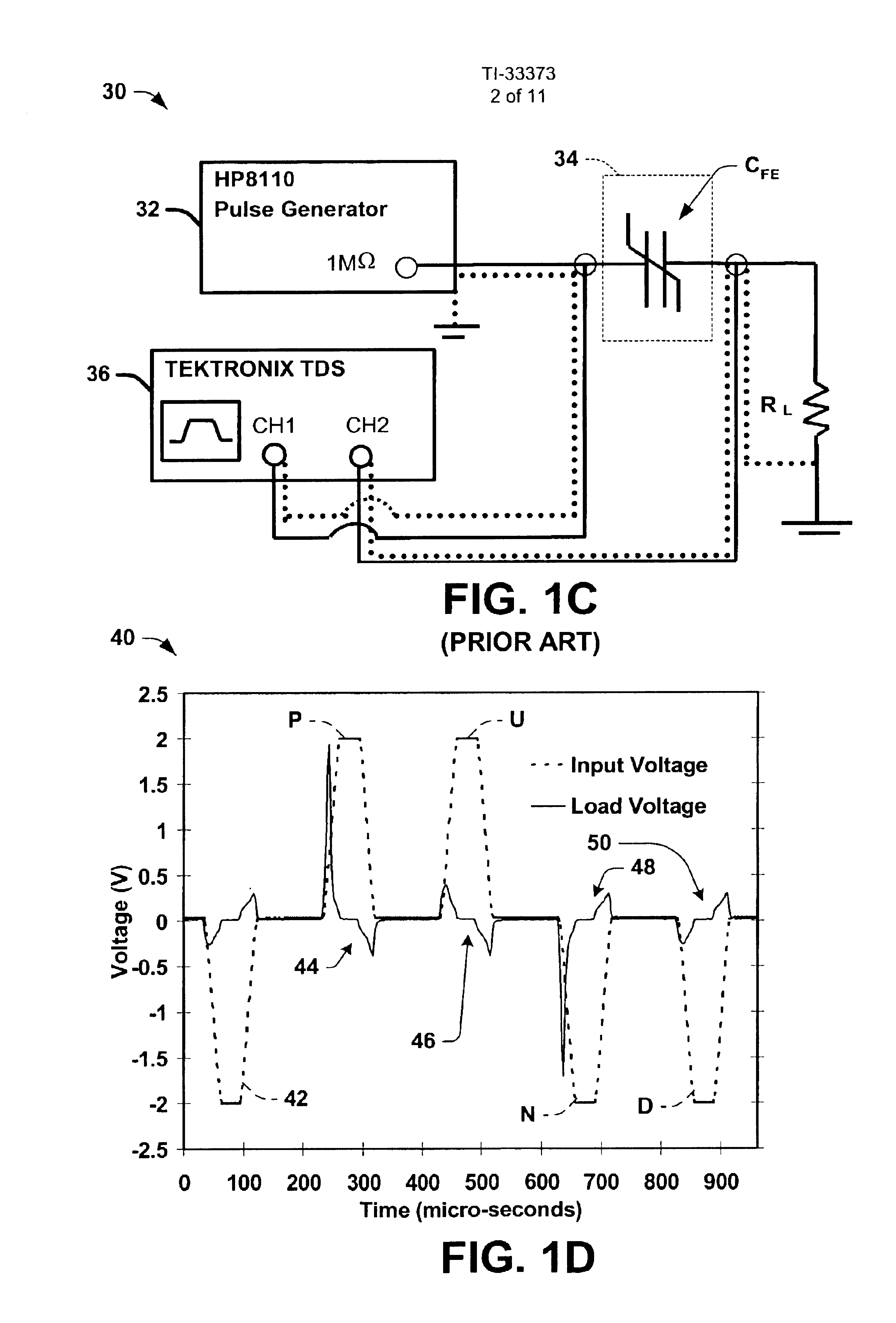
[0034]Referring initially to FIGS. 1A-1D, FIG. 1A illustrates a graph 2 ...


PUM


Abstract

Apparatus are provided for fatigue testing ferroelectric material in a wafer, including an on-chip oscillator to provide a bipolar waveform to a ferroelectric capacitor formed in the wafer, as well as a switching system to selectively provide external access to the ferroelectric capacitor. Test methods are also provided, including measuring a performance characteristic of a ferroelectric capacitor in the wafer, providing a bipolar waveform to the ferroelectric capacitor for a number of cycles using an on-chip oscillator, and again measuring the performance characteristic after an integer number of cycles of the bipolar waveform.

Description

FIELD OF INVENTION[0001]The present invention relates generally to semiconductor devices and more particularly to improved apparatus and methods for fatigue testing ferroelectric memory devices.BACKGROUND OF THE INVENTION[0002]Ferroelectric memory devices, like other semiconductor memories, are used for storing data and / or program code in personal computer systems, embedded processor-based systems, and the like. Ferroelectric memories are commonly organized in single-transistor, single-capacitor (1T1C) or two-transistor, two-capacitor (2T2C) cell configurations, in which data is read from or written to the device using address signals and various other control signals. The individual memory cells typically include one or more ferroelectric (FE) capacitors adapted to store a binary data bit, as well as one or more access transistors, typically MOS devices. The access transistor in a 1T1C configuration operates to selectively connect one terminal of the FE capacitor to one of a pair o...

Claims


Application Information

Patent Timeline
IPC IPC(8): G11C11/22H04L1/22G11C29/50
CPCG11C29/50G11C11/22G11C2029/5002
Inventor RODRIGUEZ, JOHN ANTHONYREDDY, VIJAY
Owner TEXAS INSTR INC
Learn More