
Automatic outrigger lock

a technology which is applied in the field of automatic locking and release system, can solve the problems of inability to provide an automatic locking mechanism in the prior art, and achieve the effects of convenient maintenance, superior mechanical design, and operational efficiency

Inactive Publication Date: 2005-08-16
PIPE WELDERS
View PDF14 Cites 20 Cited by
  • Summary
  • Abstract
  • Description
  • Claims
  • Application Information

AI Technical Summary

Benefits of technology

[0013]In an alternative design, the invention includes a hydraulic cylinder and piston assembly which is mounted within the coupler arm. When layout of the outrigger is desired, a control switch is used to activate the hydraulic cylinder, which results in a piston / cam assembly automatically opening the jaws to release the collar. The above-described design and specifications provide an improved automatic locking assembly for outriggers which eliminate the necessity for manual operation, such as securing an outrigger about the side of the boat utilizing ropes, mechanical latches or hinges with insert pins, bolts and nuts, or chain and hook assemblies. This frees the captain or operator to navigate the boat, attend to instrumentation or electronics, or take care of the needs of mates or guests on board. This is especially true in emergency situations.
[0015]In accordance with the instant invention, it is an object thereof to provide an improved automatic outrigger securing assembly, for use on a fishing vessel having structural support members thereon, which eliminates the requirement of manual operation.
[0018]It is a further object of the instant invention to provide an automatic outrigger securing assembly which is cost effective, and of a superior manufacturing design.
[0020]A further object of the present invention is to provide an automatic outrigger securing assembly which includes all of the above-mentioned features and objects to provide a substantially superior design, eliminating the problems encountered by prior devices, and generally solving problems associated with manual operation.

Problems solved by technology

One problem with outriggers is that they are in the extended or layout position only when fishing or trolling at relatively low speeds, such as five knots.
The prior art therefore fails to provide an automatic outrigger locking mechanism which does not require operator involvement and facilitates rapid deployment and retrieval of outriggers.

Method used


Image

  • Automatic outrigger lock
  • Automatic outrigger lock
  • Automatic outrigger lock

Examples


Embodiment Construction

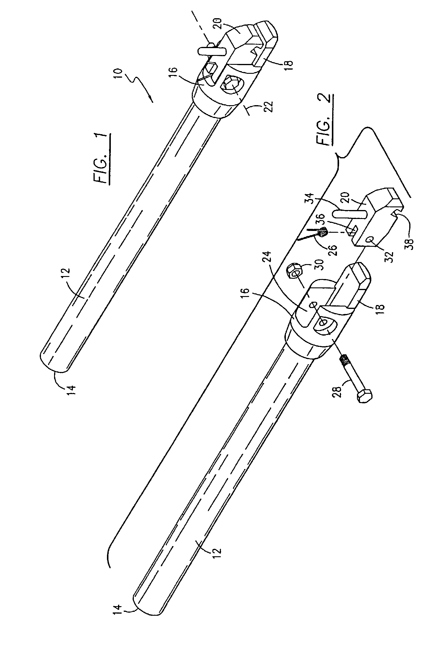
[0030]Turning to FIG. 1, an automatic outrigger securing coupling means 10 is shown, depicting the instant invention. Coupling means 10 includes support arm 12, proximate end 14 and head assembly 16.

[0031]For purposes of this disclosure, it is to be appreciated by one of ordinary skill in the marine industry, and more particularly one familiar with the design and manufacture of fishing outriggers, that outriggers are generally comprised of a main mast or pole which is extendable in a layout position for use during fishing or trolling maneuvers. Outriggers are deployed from a laydown or retracted position, where they are generally secured to a mechanism mounted on the hull of the boat, a gunnel, or alternatively about a support member located on the boat. The outrigger generally includes spreaders and guy wires which provide tension to the main outrigger mast, and prevent undesirable bending or swaying of the outrigger when in use. Conventional outriggers also include 2 or 3 support ...


PUM


Abstract

An automatic outrigger securing assembly, for use on a fishing boat which has structural support members on the vessel. The securing assembly includes a coupler for releasably securing the outrigger in a fixed position, as well as a collar assembly for interfacing with the coupler. The coupler receives and locks the collar means in a select position, and also includes a release mechanism for the collar. When the outrigger is in a laydown or collapsed configuration, the securing assembly automatically receives and safely retains the outrigger in a desired position, and can also automatically release the outrigger.

Description

BACKGROUND OF INVENTION[0001]The Present invention relates to an assembly for securing fishing outriggers, and more particularly to an automatic locking and release system, which safely and efficiently maintains fishing outriggers in secured positions, when they are in the laydown or collapsed configuration.DESCRIPTION OF RELATED ART[0002]Outrigger designs in the marine industry have heretofore addressed in general the problem of safely stowing outrigger masts, when they are not in the extended positions for use when fishing, or when the vessel is engaged in other marine activities such as kite flying. Outriggers are attached about the sides of a vessel for use in substantially extending the fishing lines away from the boat to prevent the inadvertent tangling of lines, and also to achieve a wider presentation of bait and trolling lures for game fish in order to cover a wider area of water. It is appreciated that an outrigger is separate and apart from the fishing rod and reel, and g...

Claims


Application Information

Patent Timeline
Patent Type & Authority Patents(United States)
IPC IPC(8): A01K91/08A01K91/00B63B15/00
CPCA01K91/08B63B15/00
Inventor GOEBEL, MICHAEL JRYAN, PETER D.
Owner PIPE WELDERS
Learn More