Tip for a foam-in-place dispenser

Inactive Publication Date: 2005-08-16
SEALED AIR U S
View PDF26 Cites 35 Cited by
  • Summary
  • Abstract
  • Description
  • Claims
  • Application Information

AI Technical Summary

Benefits of technology

[0022]By employing a frusto-conical shape with the outer rim extending beyond the discharge end of the dispenser, the solvent and resultant accumulation of foam residue is confined to the porous surface of the tip. This increases the effectiveness of the air/solvent mixture in removing the foam precursors and foam residue from the surface of the tip, thereby greatly exte

Problems solved by technology

One difficulty with the foamable compositions used to make polyurethane foam for foam-in-place packaging is that the foam precursors and resultant foam tend to have somewhat adhesive properties.
This tendency is particularly problematic at the discharge end of the dispenser, in which the foam precursors are mixed and from which they are ejected.
When this occurs, the hardened foam either completely occludes the tip or causes the foamable composition to be diverted in random, uncontrolled directions, i.e., not the intended direction, and generally requires

Method used


Image

  • Tip for a foam-in-place dispenser
  • Tip for a foam-in-place dispenser
  • Tip for a foam-in-place dispenser

Examples


Embodiment Construction

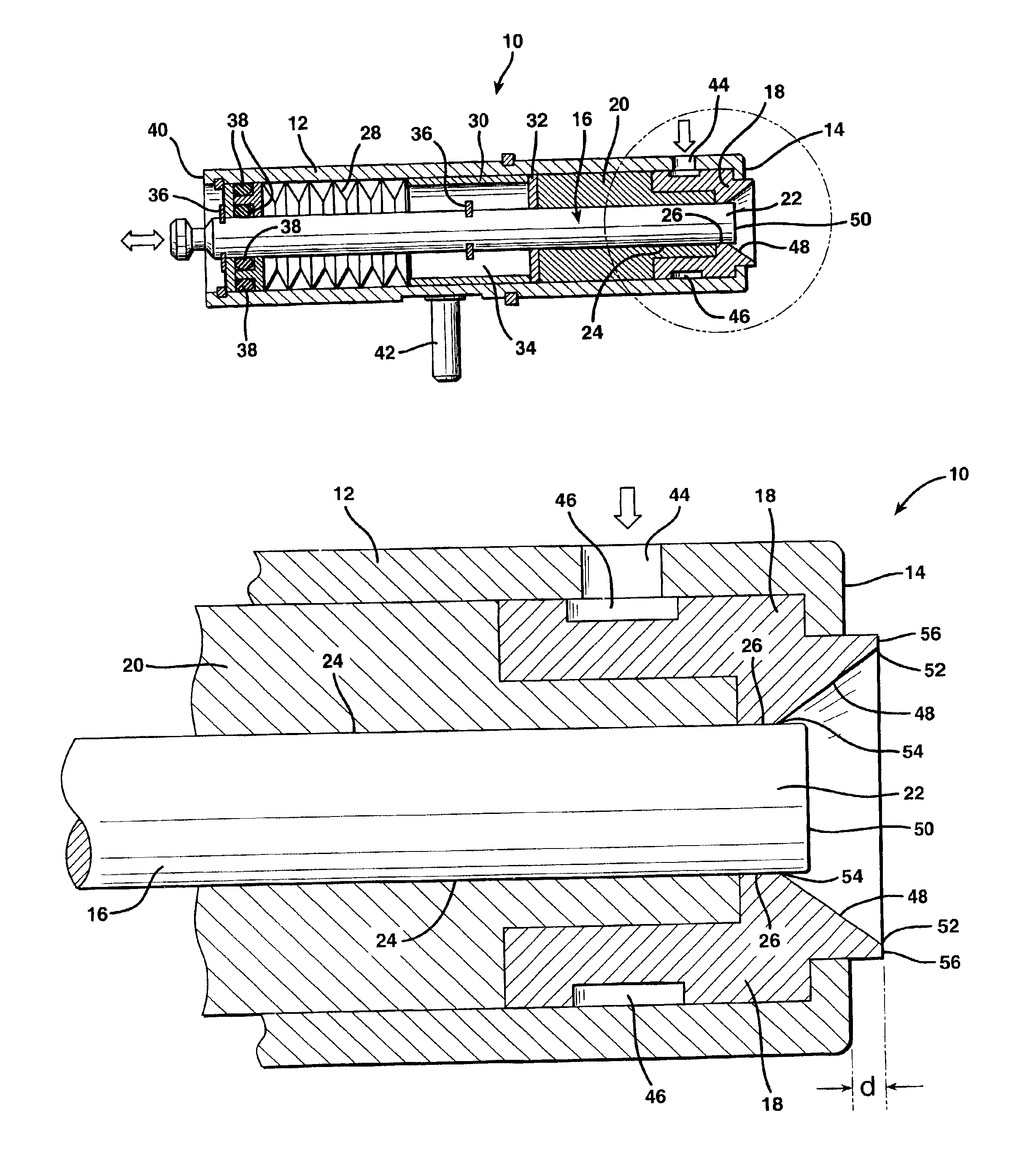
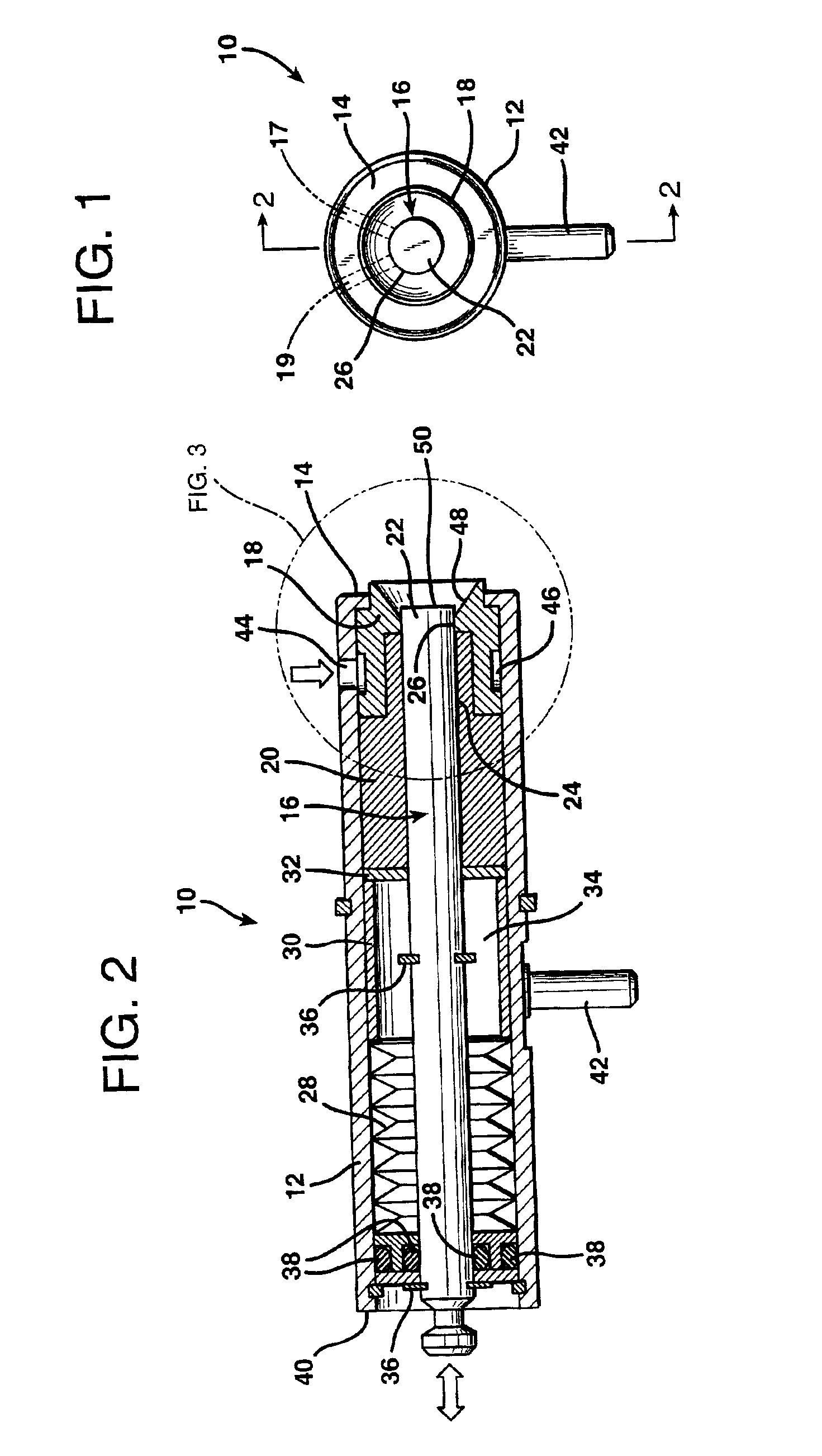
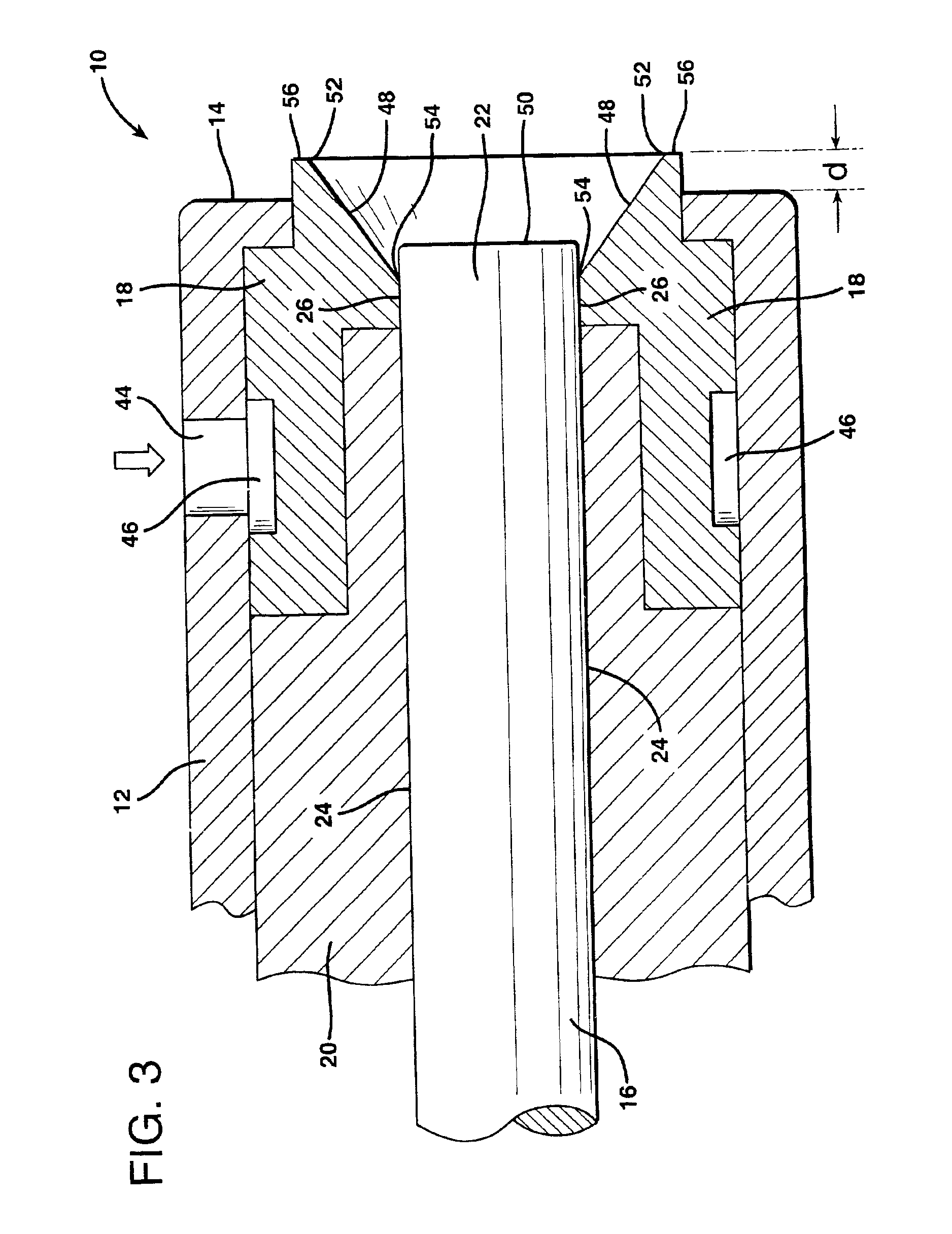
[0026]FIGS. 1 and 2 illustrate a dispenser 10 in accordance with the present invention. Dispenser 10 includes a housing 12 having a discharge end 14, a valving rod 16 disposed with the housing, and a tip 18 mounted at the discharge end 14. The dispenser also includes a pair of openings 17 and 19 through housing 12 and through core portion 20 (see FIG. 1). Core portion bears against tip 18. Valving rod 16 is axially movable within the housing, as indicated by the double-headed arrow, to control the flow of foamable compositions through the dispenser. In particular, end portion 22 of the valving rod passes through bore 24 in core portion 20 and through corresponding bore 26 in tip 18 as the valving rod moves translatably and reciprocatably through the housing. As described in the above-referenced (and incorporated) U.S. Pat. No. 5,255,847, when valving rod 16 is retracted from the position shown, foam precursors (typically a polyol and an isocyanate, both of which are under pressure) ...


PUM

PropertyMeasurementUnit
Distanceaaaaaaaaaa
Distanceaaaaaaaaaa

Abstract

A foam-in-place dispenser and a porous tip therefore having a frusto-conical face, wherein an outermost rim of the tip extends beyond the discharge end of the dispenser.

Description

BACKGROUND OF THE INVENTION[0001]The present invention pertains generally to dispensers used to produce on-demand foam-in-place packaging cushions and, more particularly, to an improved tip for such dispensers.[0002]Foam-in-place packaging is a highly useful technique for on-demand protection of packaged objects. In its most basic form, foam-in-place packaging comprises injecting foamable compositions from a dispenser into a container that holds an object to be cushioned.[0003]Typically, the object is wrapped in plastic to keep it from direct contact with the rising (expanding) foam. As the foam rises, it expands into the remaining space between the object and its container (e.g. a corrugated board box) thus forming a custom cushion for the object.[0004]A common foamable composition is formed by mixing an isocyanate compound with a hydroxyl-containing material, such as a polyol (i.e., a compound that contains multiple hydroxyl groups), typically in the presence of water and a cataly...

Claims


Application Information

Patent Timeline
IPC IPC(8): B29C44/34B29C44/36B29C39/02B29C39/22B29K75/00B29K105/04
CPCB29C44/367Y10T137/4259
Inventor RUDDY, HENRY J
Owner SEALED AIR U S
Why Eureka
Try Eureka