
Backlight assembly and liquid crystal display apparatus having the same

Inactive Publication Date: 2005-08-16
SAMSUNG DISPLAY CO LTD
View PDF4 Cites 34 Cited by
  • Summary
  • Abstract
  • Description
  • Claims
  • Application Information

AI Technical Summary

Benefits of technology

[0009]The present invention provides a backlight assembly capable of reducing power consumption and increasing brightness of a light.
[0013]Advantageously, the backlight assembly and LCD apparatus according to the present invention uses both an external light and an artificial light to display the image. Thus, to the backlight assembly and LCD apparatus may reduce power consumption and increase brightness of the light.

Problems solved by technology

However, the reflective LCD apparatuses may not display the images where an amount of the external light is not enough to display the images.
Since the transmissive LCD apparatuses use only the artificial light to display the images, the transmissive LCD apparatuses consume a lot of power.

Method used


Image

  • Backlight assembly and liquid crystal display apparatus having the same
  • Backlight assembly and liquid crystal display apparatus having the same
  • Backlight assembly and liquid crystal display apparatus having the same

Examples


embodiment 1

[0027

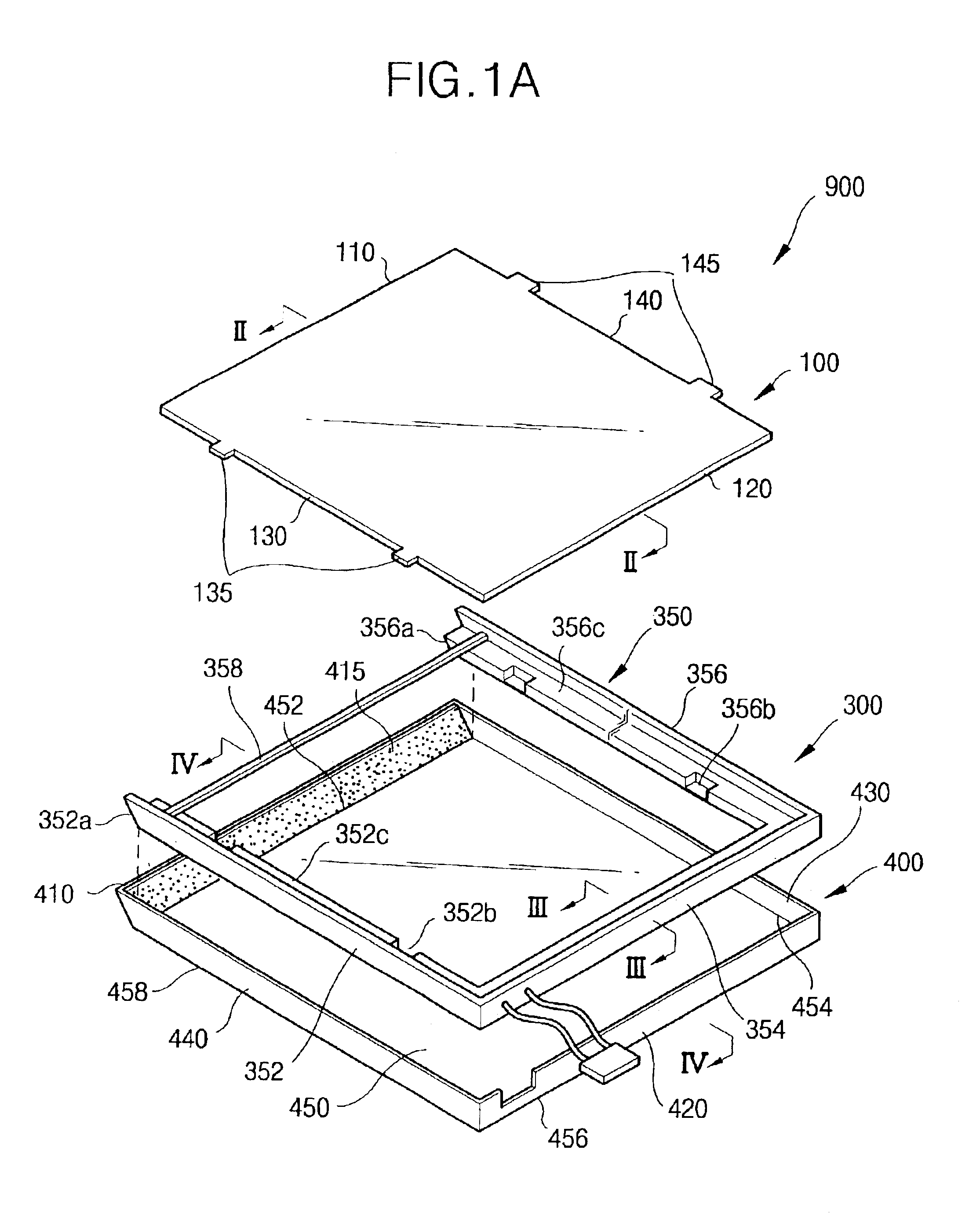
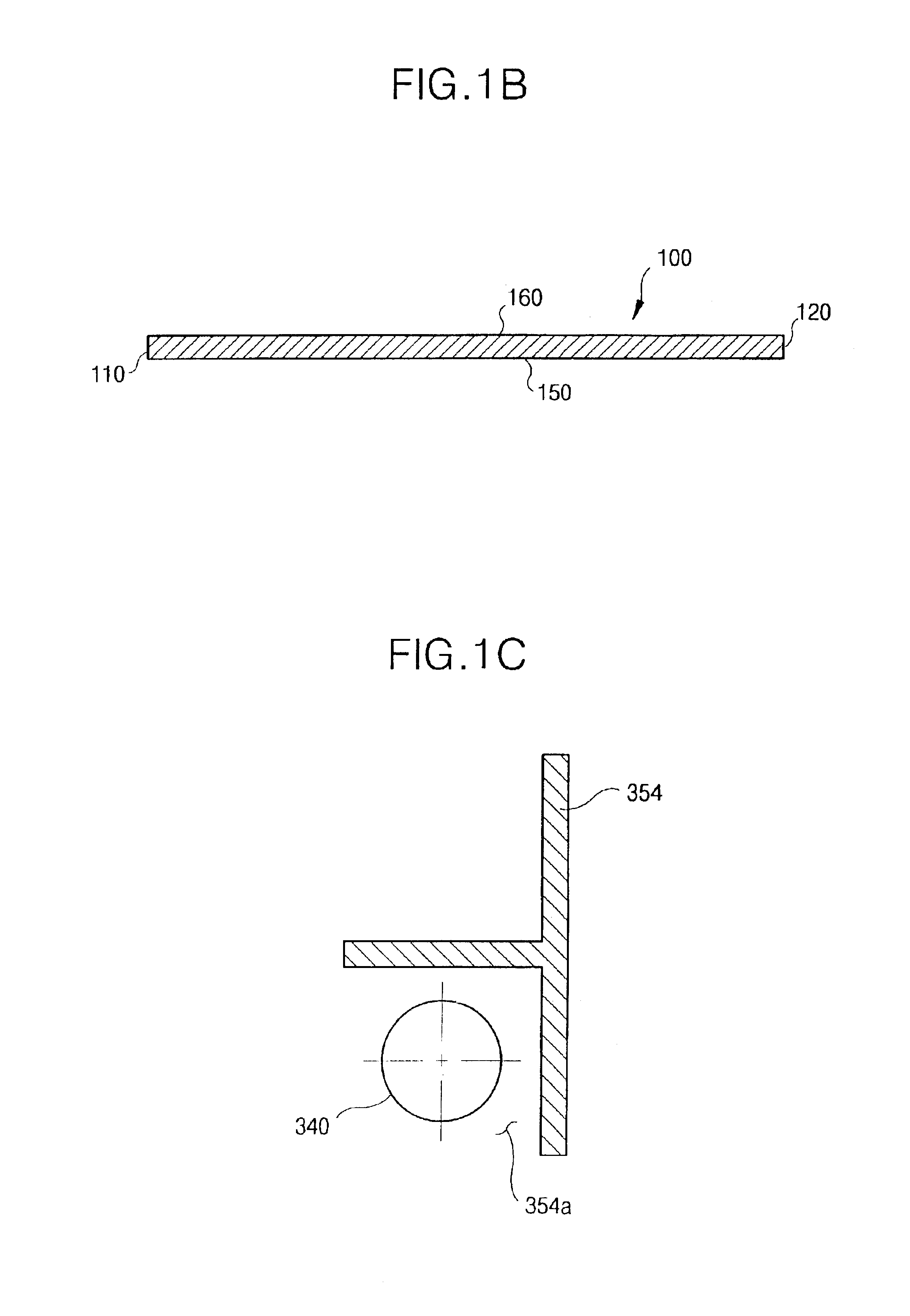
[0028]FIG. 1A is an exploded perspective view showing a backlight assembly according to a first embodiment of the present invention. FIG. 1B is a cross-sectional view taken along the line II—II for showing the light guide plate shown in FIG. 1A. FIG. 1C is a cross-sectional view taken along the line III—III for partially showing the first receiving container shown in FIG. 1A.

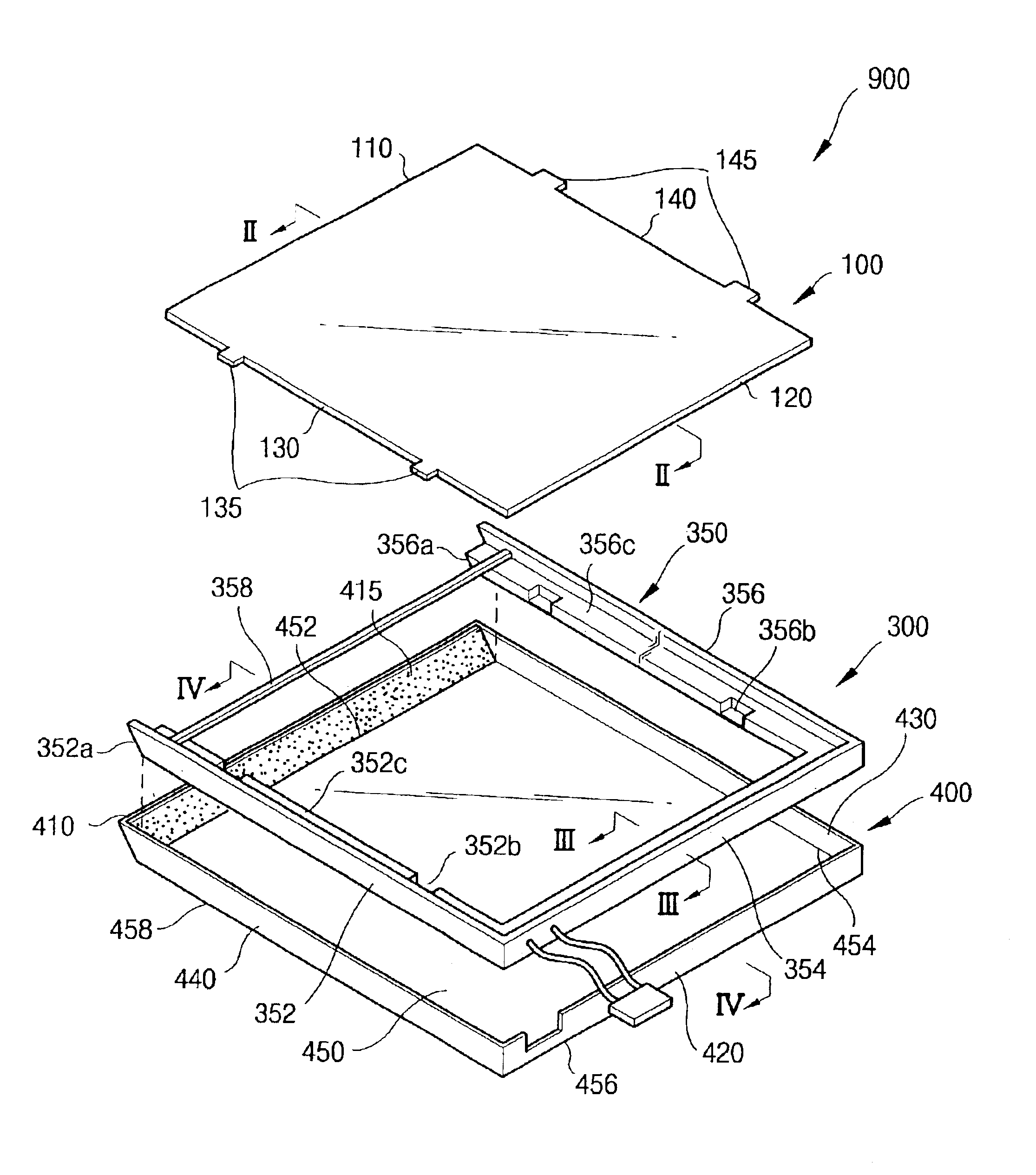
[0029]Referring to FIGS. 1A to 1C, a backlight assembly 900 comprises a lamp 340 for generating a light, a light guide plate 100 for guiding a light, a first receiving container 300 for receiving the light guide plate 100 and lamp 340, and a second receiving container 400 for receiving the first receiving container 300 and for guiding an external light to the light guide plate 100.

[0030]The light guide plate 100 may have a rectangular parallelepiped. For example, the light guide plate 100 comprises first to fourth side surfaces 110, 120, 130 and 140, a light reflecting surface 150, and a light emitting surf...

embodiment 2

[0048

[0049]FIG. 3 is an exploded perspective view showing a backlight assembly according to a second embodiment of the present invention.

[0050]A backlight assembly 900 comprises a light guide plate 100, lamp 340, first receiving container 300 and second receiving container 400. The backlight assembly 900 provides the external light and artificial light to the LCD panel to display the image. In preferred embodiments of the present invention, the backlight assembly 900 further comprises an optical sheet 200 and a reflecting plate 500 in order to display high quality image.

[0051]The optical sheet 200 comprises a diffusion sheet 240 and a prism sheet 250. The diffusion sheet 240 is disposed on the light emitting surface 160 of the light guide plate 100 to uniformly maintain brightness of the light emitted from the light emitting surface 160. The prism sheet 250 is disposed on the diffusion sheet 240 to control a direction and a visual angle of the light emitted from the diffusion sheet ...

embodiment 3

[0054

[0055]FIG. 4 is a perspective view showing a light guide plate according to a third embodiment of the present invention. FIG. 5 is a cross-sectional view taken along the line V—V for showing the light guide plate shown in FIG. 4.

[0056]A light guide plate 150 further includes an external light-lighting body 160 disposed on a first side surface 152 of the light guide plate 150.

[0057]The external light-lighting body 160 includes a first light reflecting surface 162, a second light reflecting surface 164, and a lighting surface 165.

[0058]The first light reflecting surface 162 is extended from a first edge portion 152a where a light emitting surface 154 of the light guide plate 150 comes in contact with the first side surface 152 thereof toward an upper portion of the light emitting surface 154. The first light reflecting surface 162 is perpendicular to the light emitting surface 154 and parallel to the first side surface 152. The second light reflecting surface 164 is extended from...


PUM


Abstract

A backlight assembly and an LCD apparatus capable of reducing power consumption and increasing brightness of a light. The backlight assembly includes a light guide plate for receiving an external light and an artificial light, a first receiving container for receiving the light guide plate and supplying the artificial light to the light guide plate, and a second receiving container for supplying the external light to the light guide plate, the second receiving container comprising an light side wall inclined to the light guide plate. The LCD panel assembly displays images using the external light and artificial light from the light guide plate.

Description

BACKGROUND OF THE INVENTION[0001]1. Field of the Invention[0002]The present invention relates to a backlight assembly and an LCD (Liquid Crystal Display) apparatus, and more particularly to a backlight assembly capable of reducing power consumption and increasing brightness of a light and an LCD apparatus having the same.[0003]2. Description of the Related Art[0004]LCD apparatuses typically display information such as a character, a still picture, and a moving picture by using a liquid crystal in which light transmittance is varied in response to an intensity of an electric field. The LCD apparatuses perform display operation using a light, for example, an external light such as sunshine, an illumination, etc., or an artificial light.[0005]LCD apparatuses include reflective LCD apparatuses and transmissive LCD apparatuses. The reflective LCD apparatuses display images using a reflective electrode in which sunshine or illumination is reflected to a liquid crystal. However, the reflec...

Claims


Application Information

Patent Timeline
IPC IPC(8): F21V8/00F21V31/00F21S11/00G02F1/13G02F1/1335G02B6/00G02F1/1333H01J61/40H01J61/38H01K1/26H01K1/30H01K1/00H01K1/28F21Y103/00G02F1/13357
CPCG02B6/0018G02B6/0081G02F1/133615G02B6/0066G02B6/0088G02F2001/133618G02F2001/133626G02F1/133618G02F1/133626G02F1/1335
Inventor KIM, KYU-SEOKLEE, IK-SOO
Owner SAMSUNG DISPLAY CO LTD
Learn More