Electrical contact for downhole drilling networks

a technology of electric contact and drilling network, which is applied in the direction of connection contact material, drilling pipe, coupling device connection, etc., can solve the problems of insufficient transmission of large quantities of data at high speed, inability to meet the needs of drilling operations, and many of the efforts of drilling operations have been largely abandoned or frustrated, so as to reduce the reflection of signal. , the effect of robust electrical connection

Inactive Publication Date: 2005-08-16
INTELLISERV LLC
View PDF126 Cites 168 Cited by
  • Summary
  • Abstract
  • Description
  • Claims
  • Application Information

AI Technical Summary

Benefits of technology

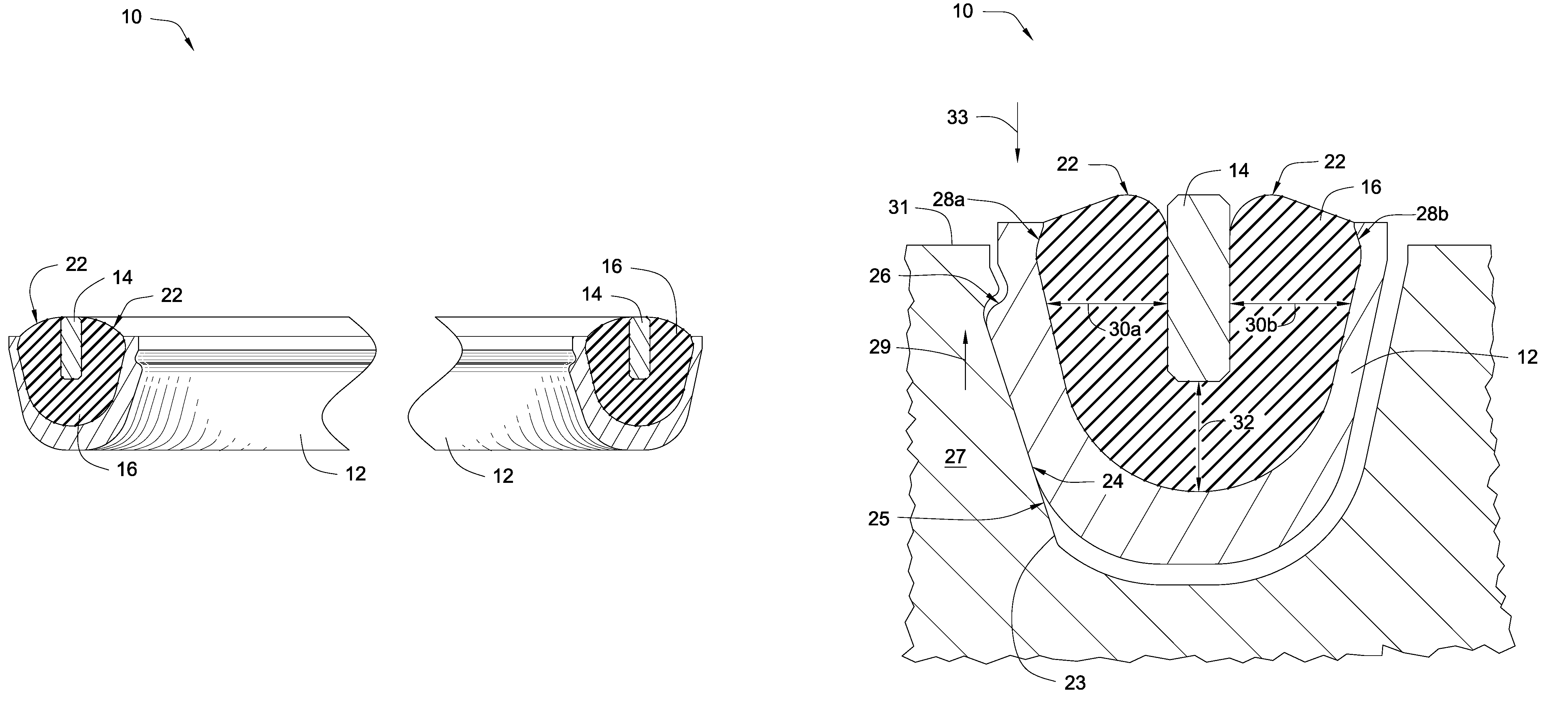
[0016]In view of the foregoing, it is a primary object of the present invention to provide apparatus and methods for reliably transmitting information between downhole tools in a drill string. It is a further object of the invention to provide robust electrical connections that may withstand the rigors of a downhole environment. It is yet another object of the invention to provide apparatus and methods to reduce signal reflections that may occur at the tool joints.
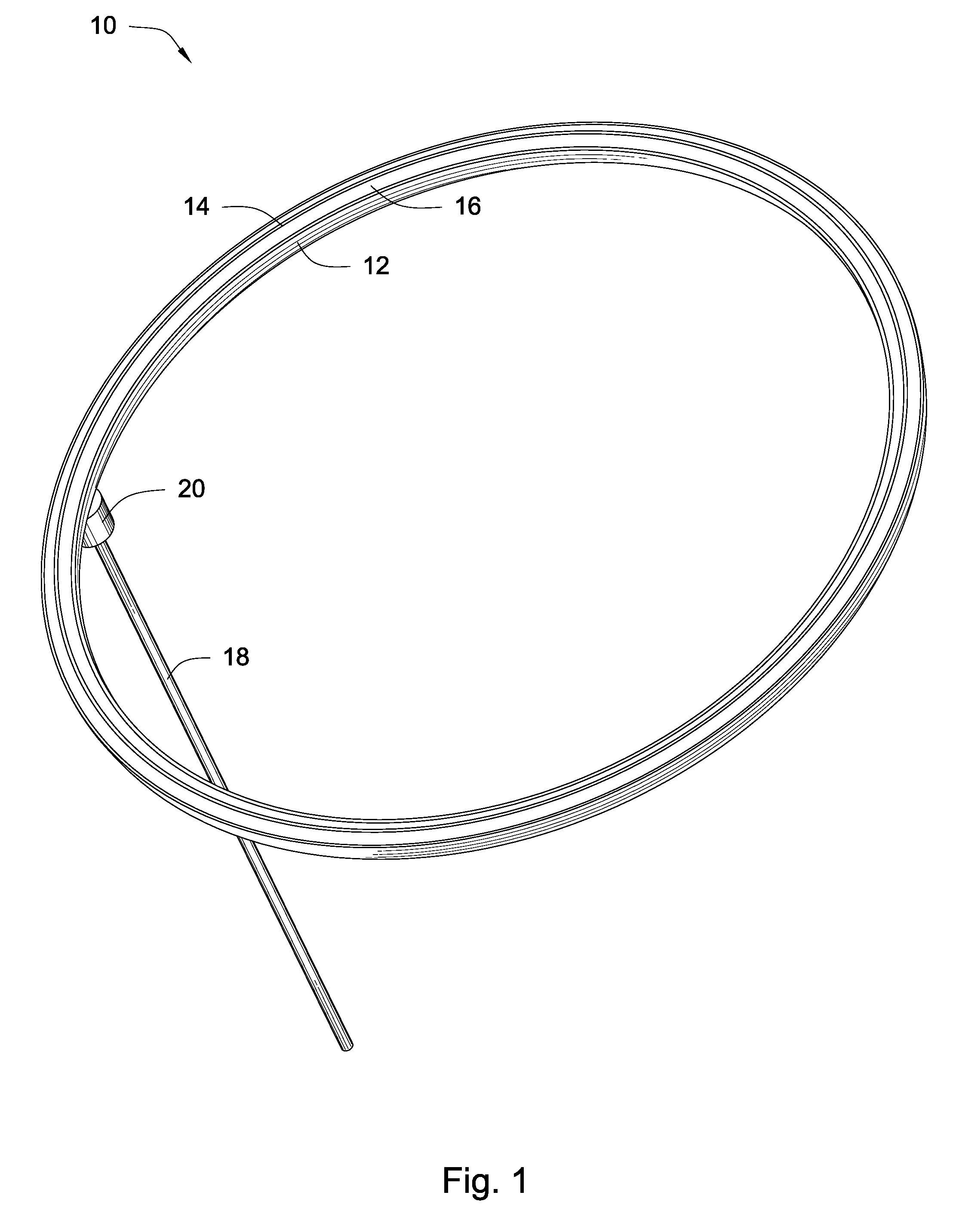
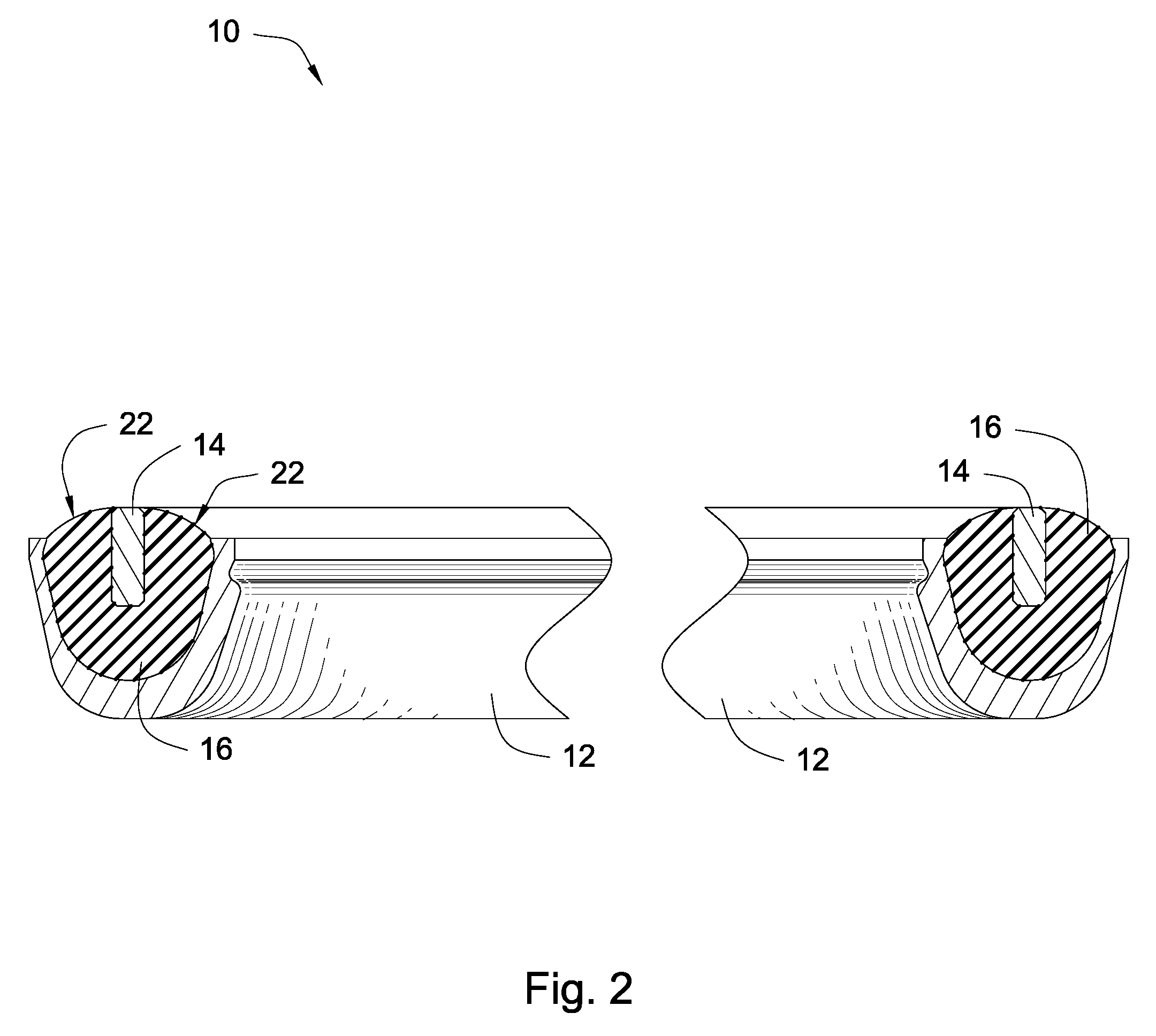
[0017]Consistent with the foregoing objects, and in accordance with the invention as embodied and broadly described herein, an electrical contact system for transmitting information across tool joints, while minimizing signal reflections that occur at the tool joints, is disclosed in one embodiment of the invention as including a first electrical contact comprised of an annular resilient material. An annular conductor is embedded within the annular resilient material and has a surface exposed from the annular resilient material.
[0019]In selected embodiments, the first and second electrical contacts further include first and second annular housings, respectively, to accommodate the annular resilient materials, and the annular conductors, respectively. In certain embodiments, the electrical contact system includes one or several biasing member to urge each of the electrical contacts together. For example, the biasing member may be a spring, an elastomeric material, an elastomeric-like material, a sponge, a sponge-like material, or the like. In other embodiments, one or both of the annular housings are sprung with respect to corresponding mating surfaces of downhole tool in which they are mounted. This may provide a biasing effect to one or both of the electrical contacts.
[0020]In selected embodiments, the first and second electrical contacts are configured such that pressure encountered in a downhole environment presses them more firmly together. In other embodiments, one or both of the electrical contacts are configured to “orbit” with respect to a mating surface of a downhole tool. By “orbiting,” it is meant that the electrical contacts may pivot along multiple axes to provide improved contact.
[0021]In certain embodiments, the annular resilient materials are constructed of a material selected to flow into voids that may or may not be present within the electrical contacts. In selected embodiments, the annular resilient material may be constructed of a material such as silicone, Vamac, polysulfide, Neoprene, Hypalon, butyl, Teflon, millable or cast polyurethane, rubber, fluorosilicone, epichlorohydrin, nitrile, styrene butadiene, Kalrez, fluorocarbon, Chemraz, Aflas, other polymers, and the like. To provide strength, durability, or other characteristics, modifiers such as Kevlar, fibers, graphite, or like materials, may be added to the annular resilient material.
[0023]In another aspect of the present invention, a method for transmitting information across tool joints in a drill string, while minimizing signal reflections occurring at the tool joints, may include providing a first electrical contact comprised of an annular resilient material, and an annular conductor embedded within the first annular resilient material. The annular conductor has a surface exposed from the annular resilient material. The method may further include providing a corresponding electrical contact substantially equal to the first electrical contact. The corresponding electrical contact also includes an annular resilient material and a second annular conductor. The method further includes adjusting the dielectric characteristics, the dimensions, or both of the annular resilient materials to provide desired impedance to the electrical contacts.

Problems solved by technology

Nevertheless, data gathering and analysis represent only certain aspects of the overall process.
However, most traditional methods are limited to very slow data rates and are inadequate for transmitting large quantities of data at high speeds.
Nevertheless, many of these efforts have been largely abandoned or frustrated due to unreliability and complexity.
A single faulty connection may break the link between downhole sensors and the surface.
Also, because of the inherent linear structure of a drill string, it is very difficult to build redundancy into the system.
The unreliability of various known contact systems is due to several factors.
First, since the tool joints are typically screwed together, each of the tools rotate with respect to one another.
This causes the contacts to rotate with respect to one another, causing wear, damage, and possible misalignment.
Since downhole tools are not typically manufactured with precise tolerances that may be required by electrical contacts, this may cause inconsistent contact between the contacts.
Moreover, the treatment and handling of drill string components is often harsh.
For example, as sections of drill pipe or other tools are connected together, ends of the drill pipe may strike or contact other objects.
Thus, delicate contacts or transmission elements located at the tool ends can be easily damaged.
This may degrade connectivity at the tools joints.

Method used


Image

  • Electrical contact for downhole drilling networks
  • Electrical contact for downhole drilling networks
  • Electrical contact for downhole drilling networks

Examples


Embodiment Construction

[0036]It will be readily understood that the components of the present invention, as generally described and illustrated in the Figures herein, could be arranged and designed in a wide variety of different configurations. Thus, the following more detailed description of embodiments of apparatus and methods of the present invention, as represented in the Figures, is not intended to limit the scope of the invention, as claimed, but is merely representative of various selected embodiments of the invention.

[0037]The illustrated embodiments of the invention will be best understood by reference to the drawings, wherein like parts are designated by like numerals throughout. Those of ordinary skill in the art will, of course, appreciate that various modifications to the apparatus and methods described herein may easily be made without departing from the essential characteristics of the invention, as described in connection with the Figures. Thus, the following description of the Figures is ...


PUM


Abstract

An electrical contact system for transmitting information across tool joints while minimizing signal reflections that occur at the tool joints includes a first electrical contact comprising an annular resilient material. An annular conductor is embedded within the annular resilient material and has a surface exposed from the annular resilient material. A second electrical contact is provided that is substantially equal to the first electrical contact. Likewise, the second electrical contact has an annular resilient material and an annular conductor. The two electrical contacts configured to contact one another such that the annular conductors of each come into physical contact. The annular resilient materials of each electrical contact each have dielectric characteristics and dimensions that are adjusted to provide desired impedance to the electrical contacts.

Description

CROSS-REFERENCE TO RELATED APPLICATIONS[0001]This application is a continuation-in-part of U.S. patent application Ser. No. 10 / 430,734 “Loaded Transducer for Downhole Drilling Components” filed on May 6, 2003 and is also a continuation-in-part of U.S. patent application Ser. No. 10 / 612,255 “Transmission Element for Downhole Drilling Components” filed on Jul. 2, 2003, which is a continuation-in-part of U.S. patent application Ser. No. 10 / 453,076 entitled “Improved Transducer for Downhole Drilling Components” filed on Jun. 3, 2003. All the above applications incorporated by reference herein for all they contain.STATEMENT OF GOVERNMENT INTEREST[0002]This invention was made with government support under Contract No. DE-FC26-01NT41229 awarded by the U.S. Department of Energy. The government has certain rights in the invention.BACKGROUND OF INVENTION[0003]1. Field of the Invention[0004]This invention relates to oil and gas drilling, and more particularly to apparatus and methods for relia...

Claims


Application Information

Patent Timeline
Patent Type & Authority Patents(United States)
IPC IPC(8): E21B17/00E21B17/02H01R13/533
CPCE21B17/003E21B17/028H01R13/533H01R2201/20E21B17/0285
Inventor HALLHALL, JR., H. TRACYPIXTON, DAVID S.DAHLGREN, SCOTTFOX, JOESNEDDON, CAMERON
Owner INTELLISERV LLC
Why Eureka
Try Eureka