
Vehicle control apparatus

Inactive Publication Date: 2005-08-16
NISSAN MOTOR CO LTD
View PDF9 Cites 56 Cited by
  • Summary
  • Abstract
  • Description
  • Claims
  • Application Information

AI Technical Summary

Benefits of technology

[0006]It has been discovered that the hybrid vehicle described in the aforementioned publication applies a braking torque to the wheels by operating the generator regeneratively when the vehicle is decelerated in response to a deceleration request corresponding to a depression of the brake pedal. As a result, the kinetic energy of the vehicle is recovered as generated electric power and the energy efficiency can be improved.
[0008]The main object of the present invention is to obtain regenerative electric power in an efficient manner by increasing the electric power generation efficiency of the motor-generators without greatly disturbing the balance between the braking torque of the rear wheels and the braking torque of the front wheels during vehicle deceleration.
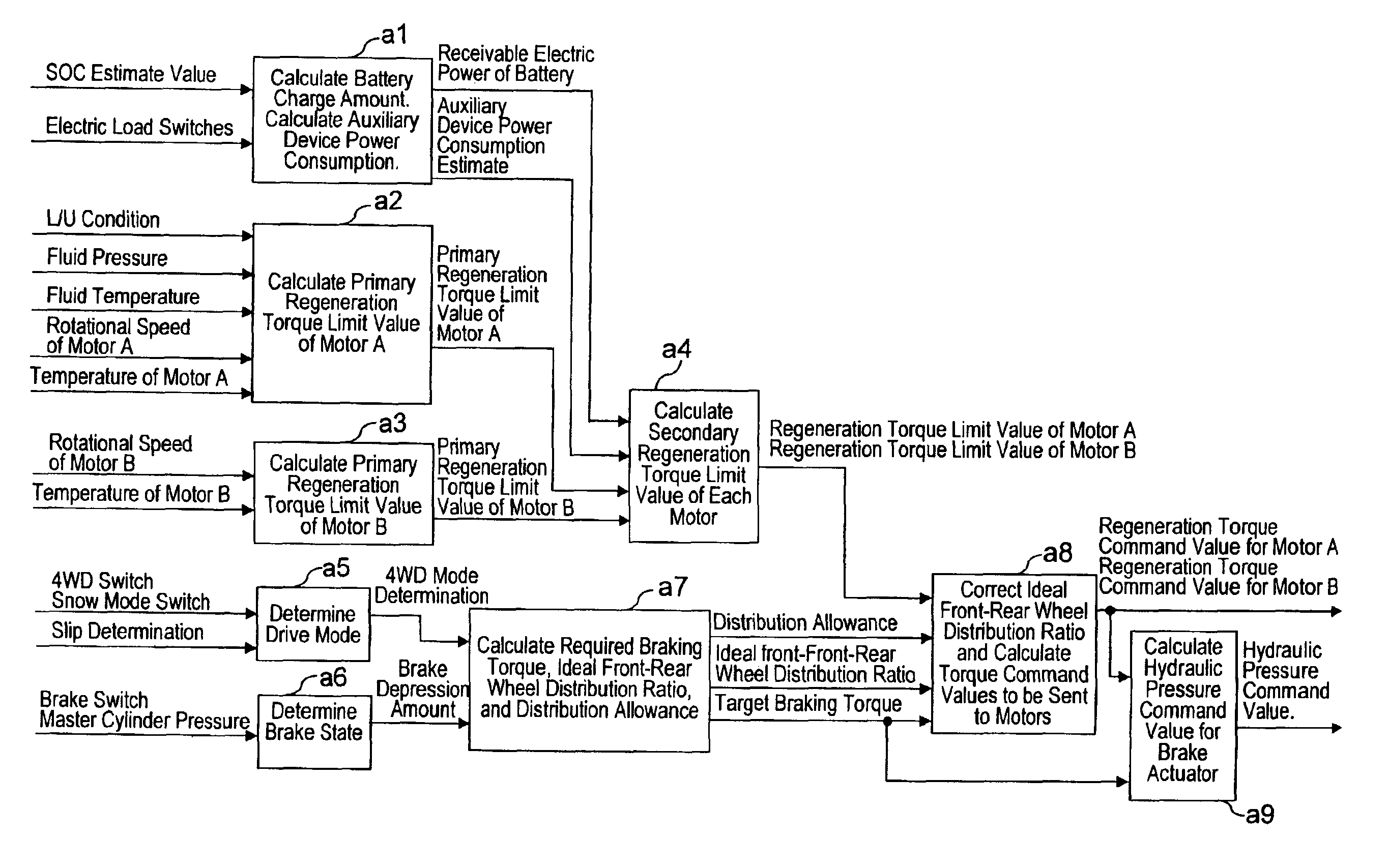
[0009]In view of the above, a vehicle control apparatus of the present invention is provided that comprises a first motor-generator, a second motor-generator, and a regenerative braking component. The first motor-generator is operatively coupled to at least one first wheel. The second motor-generator is operatively coupled to at least one second wheel that is not connected to the first motor-generator. The regenerative braking component is configured to perform regenerative braking in which a first braking torque is applied to the first wheel by regeneratively operating the first motor-generator while a second braking torque is applied to the second wheel by regeneratively operating the second motor-generator. The regenerative braking component is configured to include an ideal front-rear wheel distribution ratio calculating section, a distribution allowance calculating section, and a distribution ratio correcting section. The ideal front-rear wheel distribution ratio calculating section is configured to calculate an ideal front-rear wheel distribution ratio between the first braking torque applied to the first wheel and the second braking torque applied to the second wheel. The distribution allowance calculating section is configured to calculate a distribution allowance of the ideal front-rear wheel distribution ratio. The distribution ratio correcting section is configured to correct the ideal front-rear wheel distribution ratio within a range of the distribution allowance to increase electric power generation efficiency of at least one of the first and second motor-generators.

Problems solved by technology

However, there has not been sufficient investigation regarding the distribution ratio between the regeneration torque of the rear wheels and the regeneration torque of the front wheels during vehicle deceleration.

Method used


Image

  • Vehicle control apparatus
  • Vehicle control apparatus
  • Vehicle control apparatus

Examples


Embodiment Construction

[0021]Selected embodiments of the present invention will now be explained with reference to the drawings. It will be apparent to those skilled in the art from this disclosure that the following descriptions of the embodiments of the present invention are provided for illustration only and not for the purpose of limiting the invention as defined by the appended claims and their equivalents.

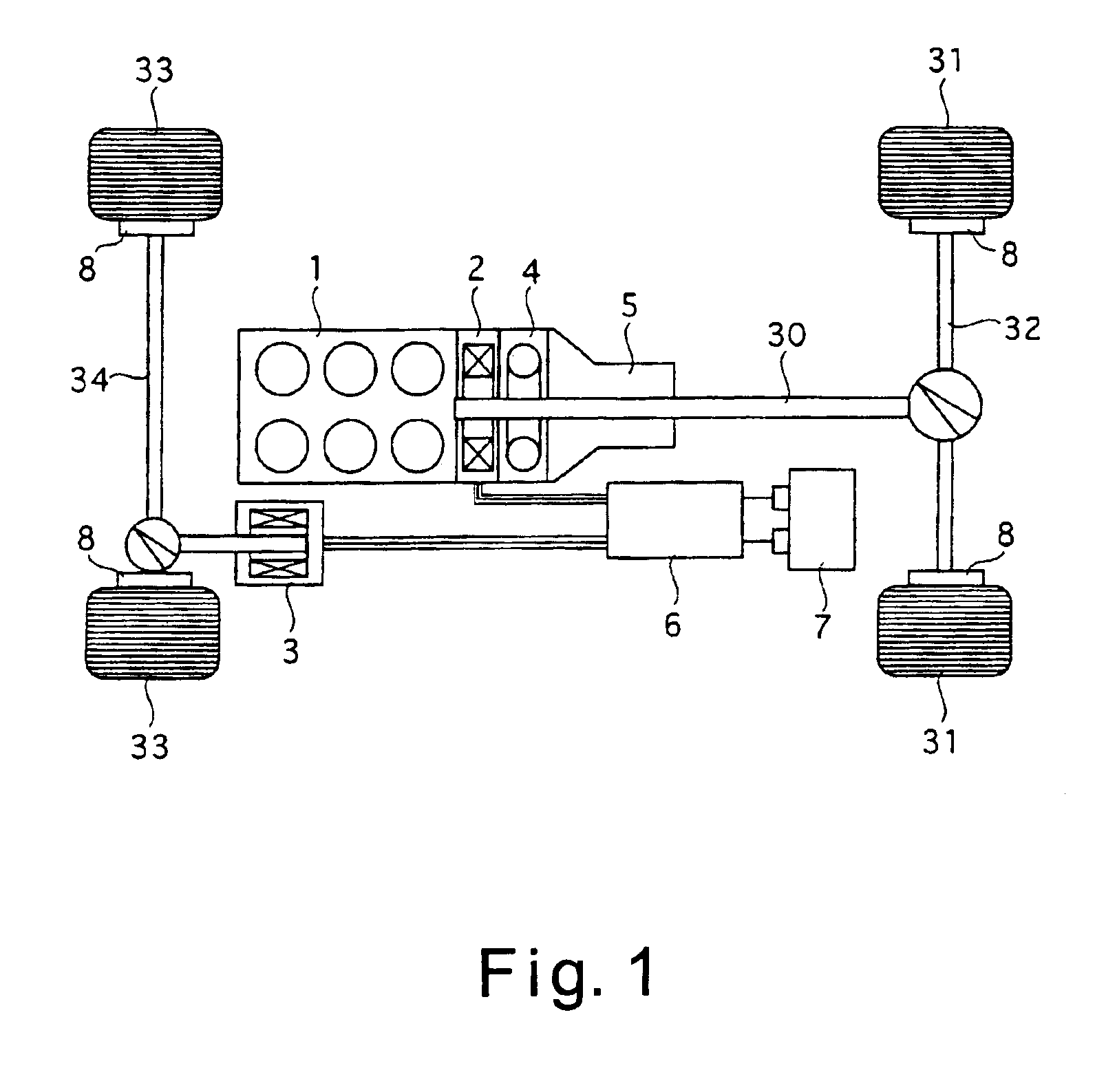
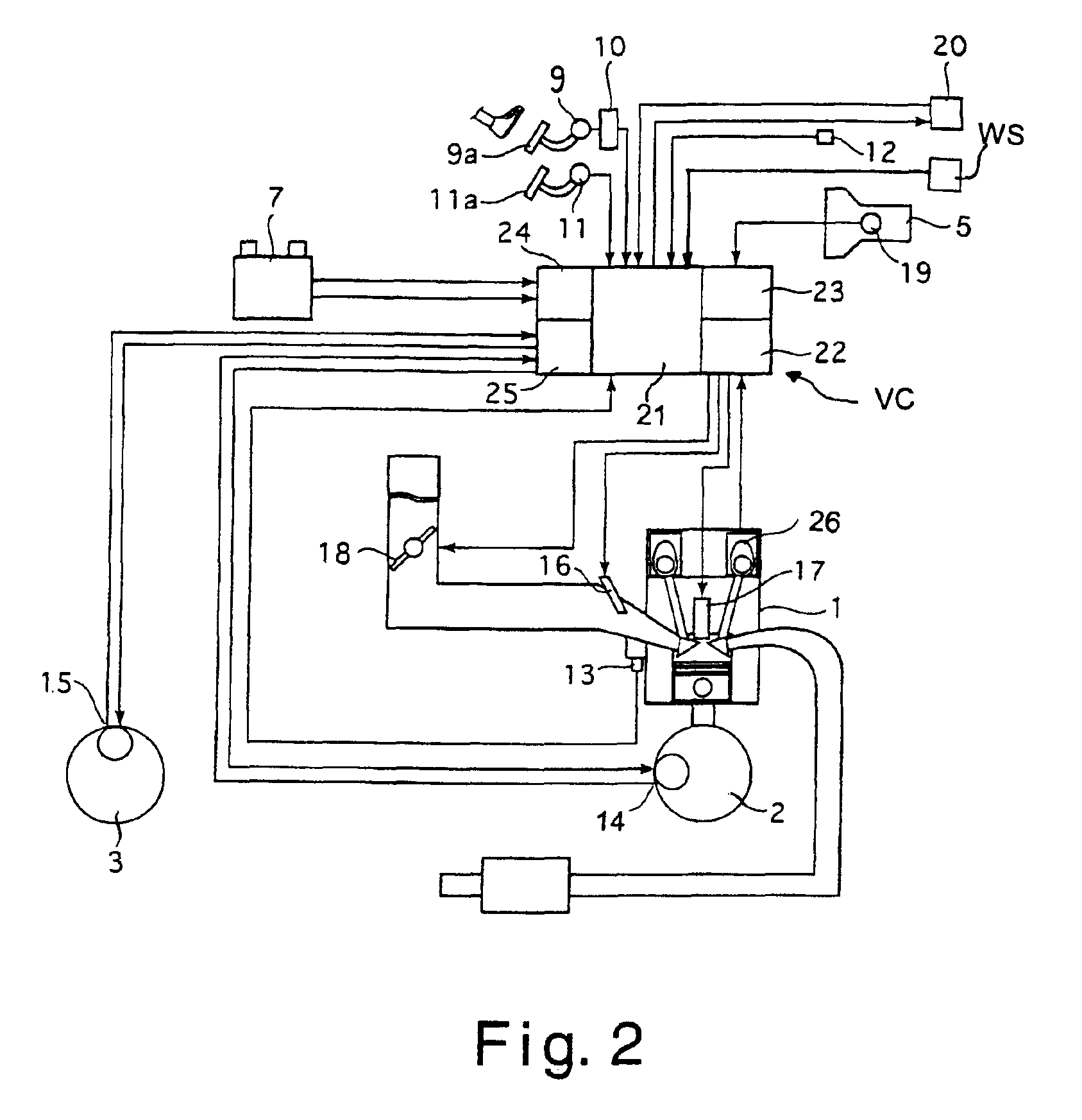
[0022]Referring initially to FIG. 1, a hybrid vehicle is illustrated as a system configuration diagram that is equipped with a control apparatus in accordance with a first embodiment of the present invention. This hybrid vehicle includes an internal combustion engine 1, a first motor-generator 2, and a second motor-generator 3 as three vehicle travel drive sources. As explained below, the control apparatus of the present invention is configured and arranged to obtain regenerative electric power in an efficient manner during vehicle deceleration by improving the electric power generation efficiency ...


PUM


Abstract

A vehicle control apparatus performs regenerative braking by regeneratively operating first and second motor-generators to apply first and second braking torques in response to a deceleration request. The vehicle control apparatus is improves the efficiency in regeneratively generating electric power without greatly disturbing the balance between the. The control apparatus calculates an ideal front-rear wheel distribution ratio for front wheel braking torque and the rear wheel braking torque, and also calculates a distribution allowance for the ideal front-rear wheel distribution ratio. The control apparatus then corrects the ideal front-rear wheel distribution ratio within the distribution allowance such that the electric power generation efficiencies of the first motor-generator connected to the rear wheels and the second motor-generator connected to the front wheels are increased. Based on the corrected front-rear wheel distribution ratio, the control apparatus calculates the torque command values to be sent to the motor-generators.

Description

BACKGROUND OF THE INVENTION[0001]1. Field of the Invention[0002]The present invention relates to a vehicle control apparatus. More particularly, the present invention relates to regeneration control of a motor-generator when a vehicle decelerates.[0003]2. Background Information[0004]In recent years, a significant amount of attention has focused on hybrid vehicles. Basically, hybrid vehicles are vehicles that use both an internal combustion engine and an electric motor as vehicle travel drive sources for the purposes of improving fuel efficiency and achieving cleaner exhaust. One example of a four-wheel drive hybrid vehicle is disclosed in Japanese Laid-Open Patent Publication No. 11-234808. This publication describes a technology in which an engine and an electric generator are connected to a pair of front wheels and an electric motor is connected to a pair of rear wheels. Thus, four-wheel drive can be accomplished by driving the electric motor with electric power regenerated by the...

Claims


Application Information

Patent Timeline
IPC IPC(8): B60K6/04B60K6/00B60K23/08B60T8/1766B60T13/58B60T13/10B60T8/26B60T7/00B60T8/17B60T8/1769B60K17/356B60K17/34B60K6/44B60K6/52B60K25/00B60W20/00B60L7/10B60L7/20B60L15/20B60L50/16B60T1/10B60W10/08B60W10/18F02D29/02
CPCB60K6/52B60K6/54B60K23/0808B60L7/10B60L7/20B60L15/2045B60T1/10B60T7/00B60T8/1766B60T8/1769B60T8/267B60T13/586B60W10/08B60W10/18B60W30/18127B60K6/44Y02T10/7283Y10T477/24B60K17/356B60K23/08B60L2240/423B60L2240/485B60T2270/608B60W2510/107B60W2520/10B60W2710/083Y02T10/56Y02T10/623Y02T10/6265Y02T10/642Y02T10/84Y02T10/40Y02T10/62Y02T10/64Y02T10/72
Inventor GUNJI, KENICHIRO
Owner NISSAN MOTOR CO LTD
Learn More