
System for testing integrated circuit devices

a technology of integrated circuit devices and test systems, which is applied in the field of semiconductor integrated circuits, can solve the problems of excessive test time for a single memory chip, high test time, and high test time, and achieve the effect of reducing time and reducing time to mark

Inactive Publication Date: 2005-08-16
CONVERSANT INTPROP MANAGEMENT INC
View PDF19 Cites 28 Cited by
  • Summary
  • Abstract
  • Description
  • Claims
  • Application Information

AI Technical Summary

Benefits of technology

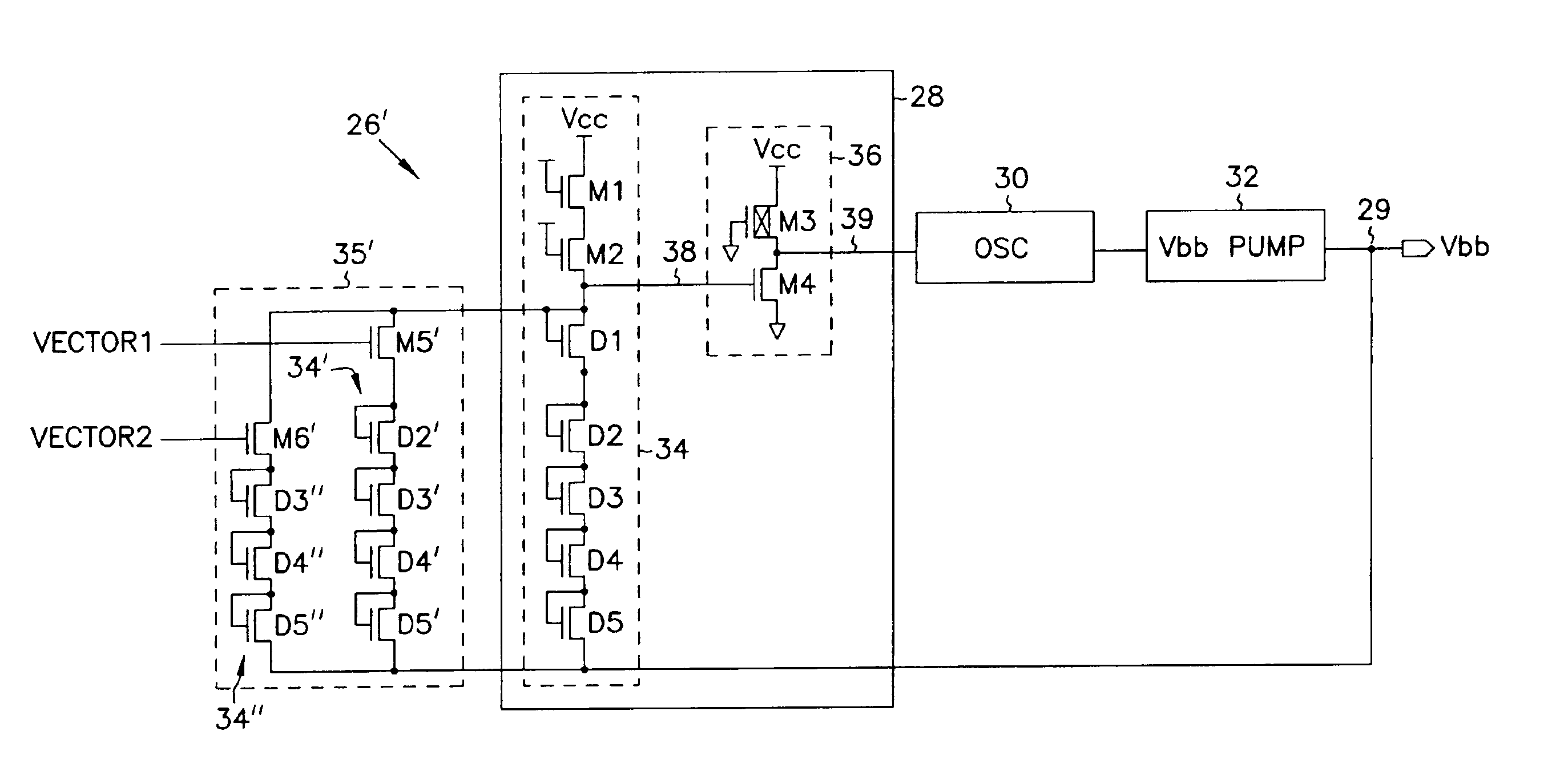
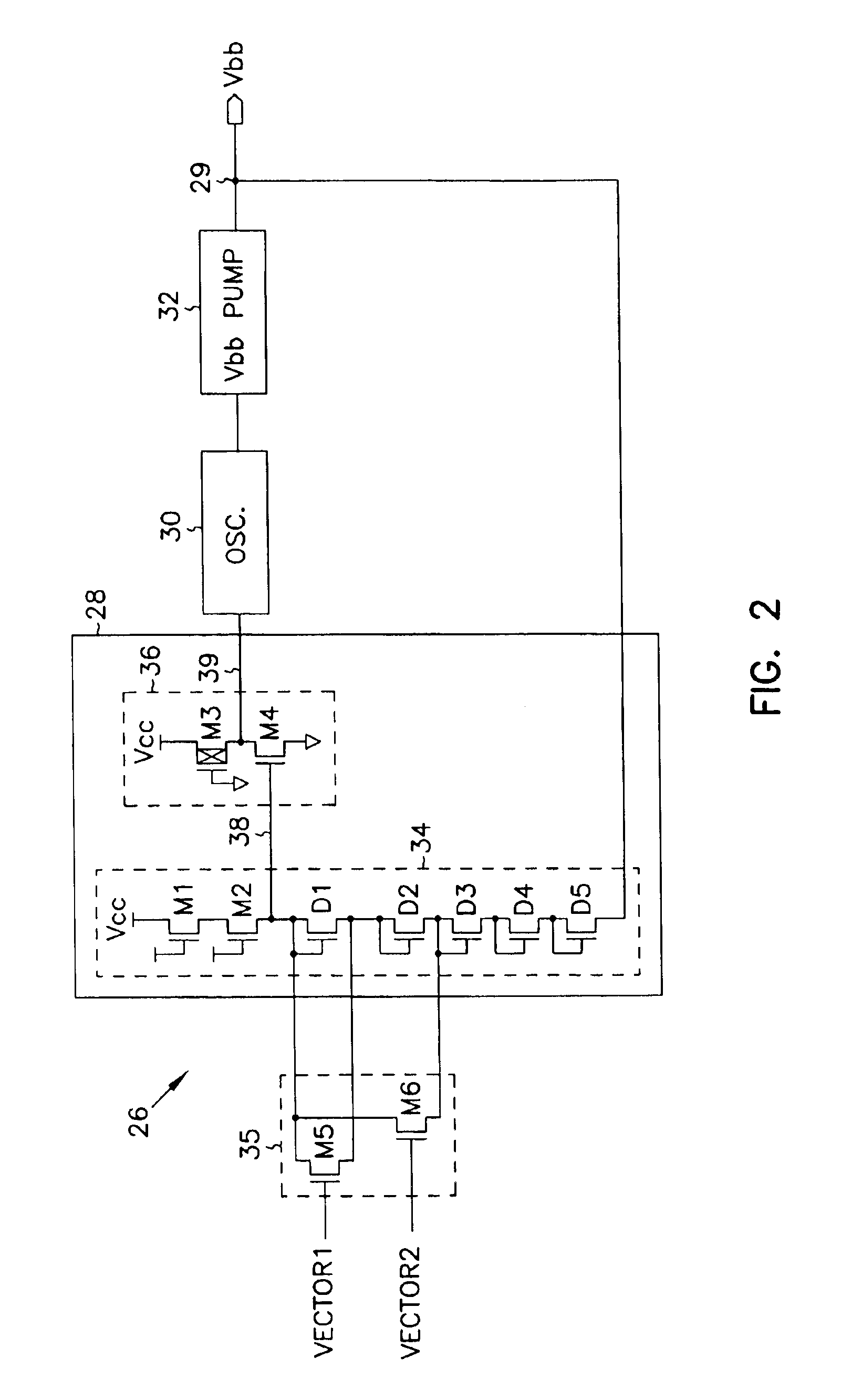
[0013]One internally generated voltage that can be controlled in accordance with the invention is the substrate voltage for the integrated circuit device. By activating different test vectors, the value of the substrate voltage will be changed. By selecting a more negative value for the substrate voltage for the static refresh test, a lower limit is set for the refresh test with an attendant reduction in the amount of time required for the refresh test. In accordance with a further embodiment, the invention enables margin testing to be carried out by controlling the voltage DVC2 used as the digitline equilibrating or cellplate bias voltage. Because no external supply voltages are required to conduct this test in accordance with the invention, the margin testings can be integrated into conventional production tests, saving time and reducing the time-to-market.
[0017]The test circuits provided by the invention provide for testing of an integrated circuit device, such as a dynamic random access memory device, by adjusting the value of internally generated voltages, such as the supply bias voltage, the digitline equilibrating voltage, or the cellplate bias voltage. Because no additional external pin is used in refresh testing of the memory device or in margin testing of the memory device, these test procedures can be integrated into the normal production tests. This will save time and the time-to-market to will be reduced.

Problems solved by technology

Consequently, testing an array of memory cells requires a substantial amount of time.
Consequently, the test time for a single memory chip can be excessive and when several hundred such chips on a wafer are tested sequentially the test time is considerable.
The requirement that solid state memory devices be tested exhaustively, and the time required to perform these tests, greatly impact on the cost of the semiconductor devices.
In many cases, this margin test procedure is conducted by hand, which is a very time intensive process.
Consequently, there is a high risk that the semiconductor device may be damaged during the testing process or in removing the packaging for conducting the margin test.
Accordingly, procedures have been developed, although not universally accepted.
One shortcoming of this arrangement is that tests that require memory read or write operations cannot be performed when externally forcing either of these pins.
As technology advances decrease the feature size of the semiconductor elements and demands are made to increase the capacity of the memory array, the memory is more prone to defects that damage memory cells of memory devices.

Method used


Image

  • System for testing integrated circuit devices
  • System for testing integrated circuit devices
  • System for testing integrated circuit devices

Examples


Embodiment Construction

[0029]In the following detailed description of the preferred embodiments, reference is made to the accompanying drawings which form a part hereof, and in which is shown by way of illustration specific preferred embodiments in which the invention may be practiced. The preferred embodiments are described in sufficient detail to enable those skilled in the art to practice the invention, and it is to be understood that other embodiments may be utilized and that logical changes may be made without departing from the spirit and scope of the present invention. The following detailed description is, therefore, not to be taken in a limiting sense, and the scope of the present invention is defined only by the appended claims.

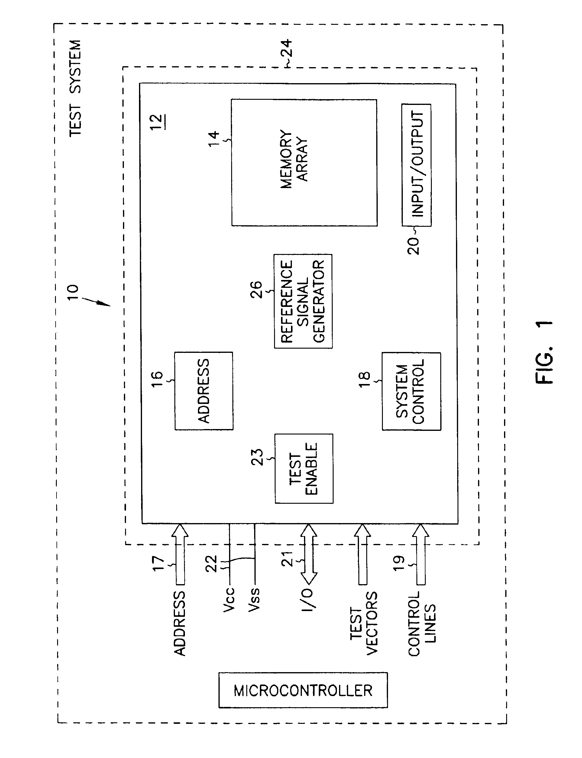
[0030]Referring to FIG. 1 of the drawings, the reference signal generating circuit provided by the invention is described with reference to an application in an integrated circuit memory device such as, a dynamic random access memory (DRAM) device. However, the reference ...


PUM


Abstract

A voltage generating circuit for generating internal voltage for a packaged integrated circuit memory device, is controllable to provide incremental adjustments in the voltage for testing of the memory device. The voltage generating circuit permits internally generated voltages of the memory device, such as the substrate voltage Vbb, the DVC2 voltage, and the pumped voltage Vccp, to be controlled externally through the application of test signals via the conventional test function, in performing standard device tests such as the static refresh test, logic 1s and 0s margin testing, and the like for packaged memory devices. Also, programmable circuits including programmable logic devices, such as anti-fuses, are provided that are programmable to maintain the voltage at a magnitude to which it is adjusted.

Description

[0001]This application is a Continuation of U.S. application Ser. No. 10 / 295,499, filed Nov. 15, 2002, now U.S. Pat. No. 6,756,805 which is a Divisional of U.S. application Ser. No. 08 / 916,994, filed Aug. 21, 1997, now U.S. Pat. No. 6,496,027, both of which are incorporated herein by reference.FIELD OF THE INVENTION[0002]The present invention relates to semiconductor integrated circuits, and in particular, the invention relates to a method and a voltage generating circuit for allowing packaged part testing of semiconductor integrated circuits by controlling internal voltages of the integrated circuits.BACKGROUND OF THE INVENTION[0003]Semiconductor integrated circuit devices, such as dynamic random access memory (DRAM) devices, undergo a tremendous amount of testing at various steps in the production process. Typically, DRAM devices are tested by using write and read operations to determine whether all of the cells of the memory array can properly store data signals and whether the d...

Claims


Application Information

Patent Timeline
IPC IPC(8): G01R31/30G01R31/28G11C5/14G11C29/12G11C29/04G01R31/26G11C29/02
CPCG01R31/3004G11C5/145G11C5/146G11C29/02G11C29/021G11C29/028G11C29/12G11C29/12005G11C2029/5004
Inventor SHER, JOSEPH C.SIEK, DAVID D.VO, HUY THANHVAN HEEL, NICHOLASWONG, VICTORZHENG, HUA
Owner CONVERSANT INTPROP MANAGEMENT INC
Learn More