
Modular electrotactile system and method

Inactive Publication Date: 2005-08-16
OWNWAY BIOTRONICS
View PDF15 Cites 79 Cited by
  • Summary
  • Abstract
  • Description
  • Claims
  • Application Information

AI Technical Summary

Benefits of technology

[0012]In accordance with the invention, an electrotactile module for delivering tactile stimuli to a skin surface of a user is provided. The module comprises a housing having a first surface and a second surface, an array of electrodes a

Problems solved by technology

However, these interface devices are typically bulky or awkward to use or are adapted for very specific applications.
Most prior art haptic systems developed thus far do not stimulate human skin mechanoreptors selectively or precisely.
Such systems are therefore unsuitable for virtual reality and similar applications where fidelity of tactile sensations is critical.
Previous artificial tactile displays of this sort have been limited primarily to homogenous arrays of relatively small vibrators that provide low-amplitude, high frequency stimulation of the tactile system.
Such vibrotactile systems are useful for some applications, but they do not enable a highly sensitive localized response.
Most devices are not designed to selectively stimulate all four types of mechanoreceptors in the human skin described above.
Moreover, the current applied is pre-programmed and there is no provision for adjustment of the current parameters based on user interactivity or other variable data input.
Although there is a growing awareness of the advantages of electro-neuromodulation therapy for medical or rehabilitative purposes, thus far electrotactile or electrocutaneous devices have not been effectively applied in the information and entertainment industries, such as part of a virtual reality computer application.

Method used


Image

  • Modular electrotactile system and method
  • Modular electrotactile system and method
  • Modular electrotactile system and method

Examples


Embodiment Construction

[0047]This application relates a modular electrotactile system and method. As used in this patent application the term “electrotactile” refers to the use of electrical stimuli to induce a tactile sensation in a user, such as a sensation of touch or pressure. The terms “electrotactile device” or “electrocutaneous device” both refer to an apparatus that activates nerve axons in the skin by applying electric current directly to the skin surface.

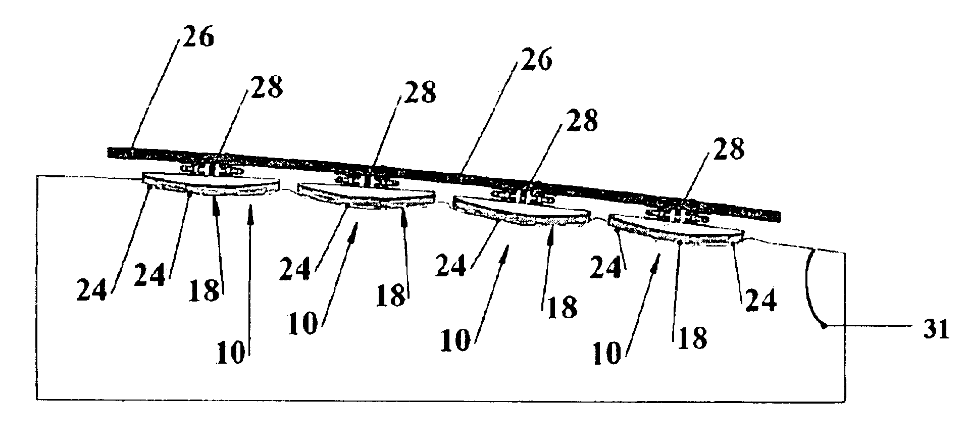
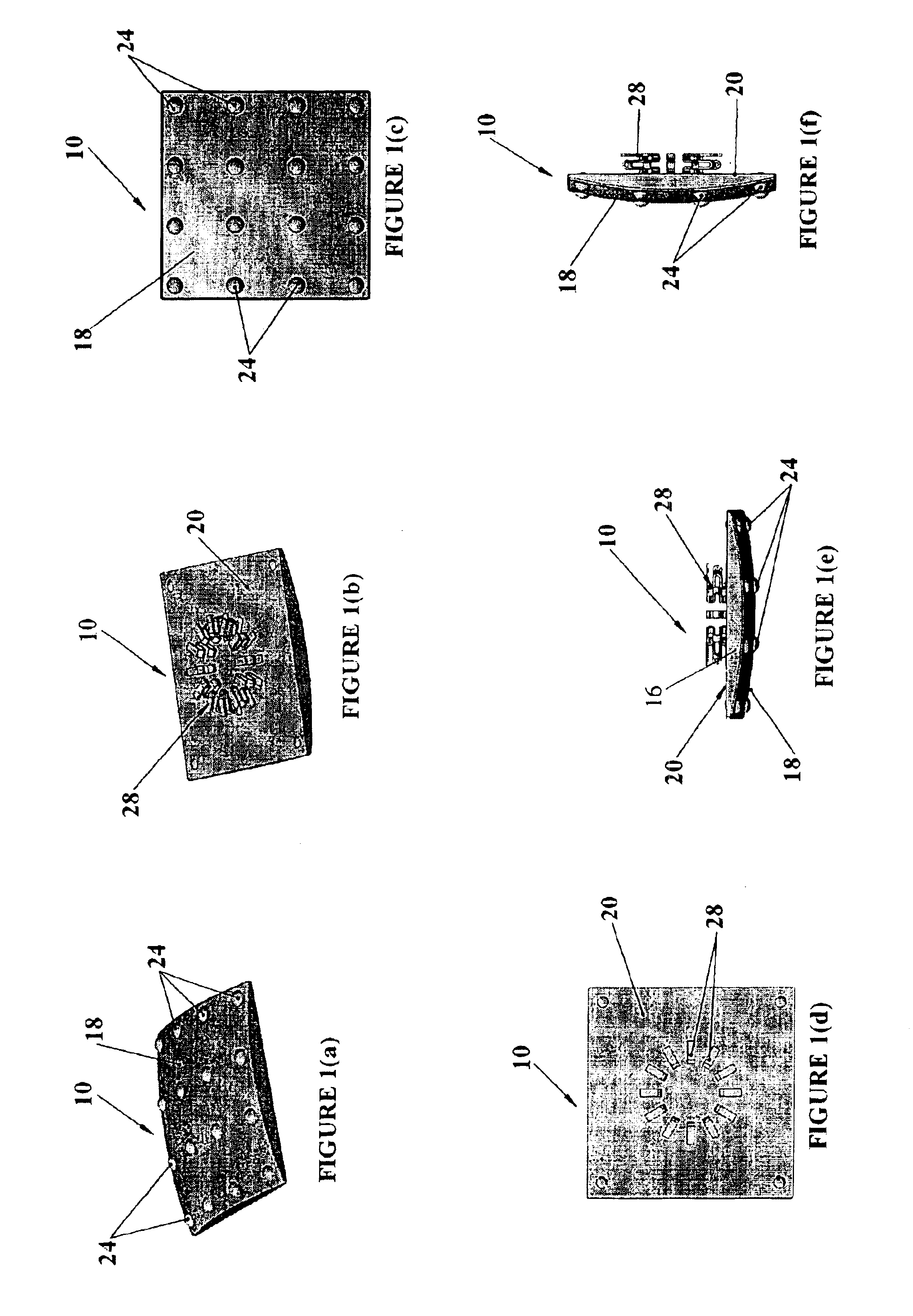
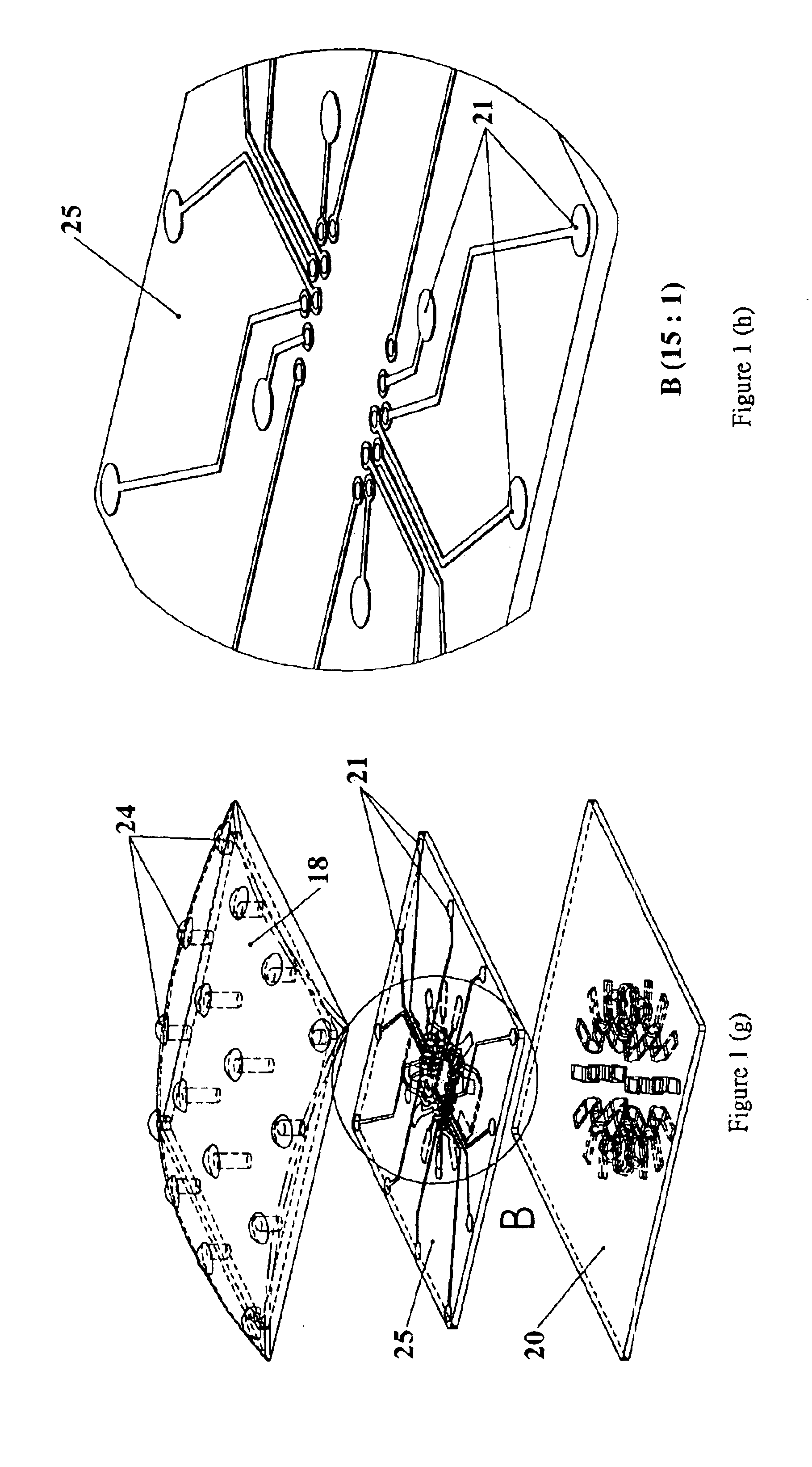
[0048]FIGS. 1(a)-1(j) illustrate an electrotactile module 10 developed by the applicant for delivering tactile stimuli to a user. A plurality of modules 10 may be assembled together to form an integrated electrotactile device 12 as shown in FIGS. 3(a)-3(e). Further, a plurality of devices 12 may be deployed in a wearable article 14 for placement in contact with a skin surface of a user as illustrated in FIGS. 4(a)-4(d).

[0049]As shown best in FIGS. 1(a)-1(j), each electrotactile module 10 comprises a thin housing 16 having a first surface 18 and ...


PUM


Abstract

This application relates to an electrotactile system and method for delivering tactile stimuli to a skin surface of a user. The system includes one or more electrotactile modules each comprising an array of electrodes electrically connected to an integrated circuit. Each integrated circuit has data processing and current driving capability. The current delivered from the integrated circuit to each electrode is relatively small, preferably less than 4 milliamps. The modules may be connected to a flexible PC board by spring-loaded connectors. In one embodiment a plurality of electrotactile modules may be grouped together to from an electrotactile device. Multiple electrotactile devices may in turn be deployed as part of a wearable article for use in virtual reality, telepresence, telerrobotics or other haptic feedback applications. The system is capable receiving and transmitting tactile data via a communication link, such as a conventional data network. For example, tactile data can be transmitted in a scalable streaming format from a remote site to the system via a data network. The system may form part of a virtual reality entertainment application.

Description

TECHNICAL FIELD[0001]This application relates to an electrotactile system and method for delivering tactile stimuli to a skin surface of a user. The system comprises electrotactile modules each comprising an integrated circuit electrically connectable to an array of electrodes. The modules may be connected together to form an electrotactile device. A plurality of devices may in turn be deployed as part of a wearable article for use in virtual reality, telepresence, telerrobotics or other haptic feedback applications. The system is capable of receiving and transmitting data via a communication link.BACKGROUND[0002]Interactive haptic feedback systems are known in the prior art for delivering tactile data to a user, such as sensations of force and touch. For example, haptic feedback has been used in the past in various aerospace, surgical and defence applications for the purpose of controlling remote robotic vehicles and manipulators. More recently, haptic feedback has been used in tel...

Claims


Application Information

Patent Timeline
IPC IPC(8): H04B3/36G06F3/01G09B21/00
CPCG06F3/016G09B21/003
Inventor LING, SHO-HUNG WELKINCHANG, CHI-CHIALIN, WANCHIH
Owner OWNWAY BIOTRONICS
Learn More