Three dimensional sensor laser noise reduction method

a three-dimensional sensor and laser noise reduction technology, applied in the direction of distance measurement, height/levelling measurement, instruments, etc., can solve the problems of limiting the system performance, adding additional sources of error, reducing the available light energy received by the detector, etc., to reduce speckle noise, eliminate mechanical motion errors, and maximize the effect of detectable laser ligh

Inactive Publication Date: 2005-08-16
GENERAL ELECTRIC CO
View PDF7 Cites 1 Cited by
  • Summary
  • Abstract
  • Description
  • Claims
  • Application Information

AI Technical Summary

Benefits of technology

[0005]Briefly stated, the present invention uses a combination of a detector lens f-number, data regarding object surface scatter, and laser coherence control, to reduce speckle noise in a structured light gauge measurement system. This is done without use of moving mechanical parts, thereby eliminating mechanical motion errors and maximizing detectable laser light.

Problems solved by technology

However, laser lines used in structured light systems for measurement gauging of objects contain coherent noise, such as speckle, which limits the performance of the system.
While these methods average out the coherent speckle noise, they reduce available light energy received by the detectors, and add additional sources of error associated with the position of the line due to the wobble present in the mechanical scanning or dithering systems.

Method used


Image

  • Three dimensional sensor laser noise reduction method
  • Three dimensional sensor laser noise reduction method

Examples


Embodiment Construction

[0012]The following detailed description illustrates the invention by way of example and not by way of limitation. The description clearly enables one skilled in the art to make and use the invention, describes several embodiments, adaptations, variations, alternatives, and uses of the invention, including what is presently believed to be the best mode of carrying out the invention.

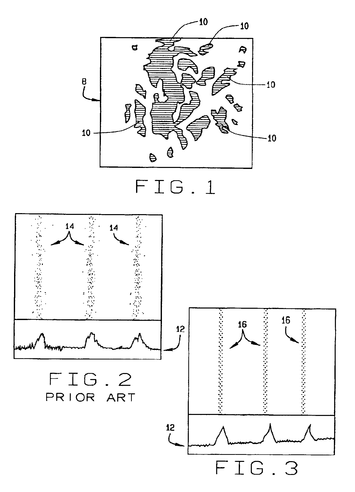
[0013]Laser light reflected and scattered from the surface of an object 8 is perceived by detectors in an optical measurement system as individual points or spots 10 of light and dark contrast, known as “speckle”, shown in FIG. 1. Classic “speckle” noise is a light interference phenomena dependent upon the wavelength and aperture size of the viewing system. Therefore, a low lens f-number on the detector typically reduces the size of observed speckles 10. For example, a f / 2 lens system produces speckles 10 which are approximately 2.3 microns in size, from light projected onto a uniform scattering surface s...


PUM


Abstract

A method for improving the accuracy of measurements made in non-contact gauging an object utilizing a detector to observe a laser line projected onto a surface of the object. A combination of detector lens f-number adjustments, surface scatter statistics, and laser coherence control are utilized to reduce speckle noise in the structured light gauge measurement system without the use of moving mechanical parts. This eliminates added mechanical motion errors and maximizes detectable laser light.

Description

BACKGROUND OF THE INVENTION[0001]The use of laser lines as a tool for non-contact measurement gauging of an object is well established. Laser lines are projected onto the object being gauged, and an image of the projected lines is observed by one or more detectors for use in triangulation measurements. However, laser lines used in structured light systems for measurement gauging of objects contain coherent noise, such as speckle, which limits the performance of the system.[0002]One approach to increase the measurement accuracy of laser based measurement gauges has been to reduce the size of the laser spot or laser line thickness projected onto the surface of the object undergoing measurement gauging. However, in the case of a smaller projected spot or thinner line projection, on the order of a few tens of microns in diameter or cross-section, the coherent speckle created by the surface characteristics of the object onto which the laser is projected can become very large, even compar...

Claims


Application Information

Patent Timeline
Patent Type & Authority Patents(United States)
IPC IPC(8): G01B11/25G01B11/24
CPCG01B11/2518
Inventor HARDING, KEVIN GEORGE
Owner GENERAL ELECTRIC CO
Why Eureka
Try Eureka