Miniaturized holographic fourier transform spectrometer with digital aberration correction

a fourier transform spectrometer and digital aberration technology, applied in the field of optical spectrometers, can solve the problems of greatly degraded optical resolution and distortion of frequency spectrum

Active Publication Date: 2005-08-16
CORNELL RES FOUNDATION INC
View PDF8 Cites 12 Cited by
  • Summary
  • Abstract
  • Description
  • Claims
  • Application Information

AI Technical Summary

Benefits of technology

[0012]The present invention suggests a simple way of correcting these aberrations by rescaling the interference pattern to compensate for the distortion. The result will straighten the interference fringes.

Problems solved by technology

In the presence of optical aberrations the interference pattern is distorted and the same Fourier transformation results in a distorted frequency spectrum with greatly degraded optical resolution.

Method used


Image

  • Miniaturized holographic fourier transform spectrometer with digital aberration correction
  • Miniaturized holographic fourier transform spectrometer with digital aberration correction
  • Miniaturized holographic fourier transform spectrometer with digital aberration correction

Examples


first embodiment

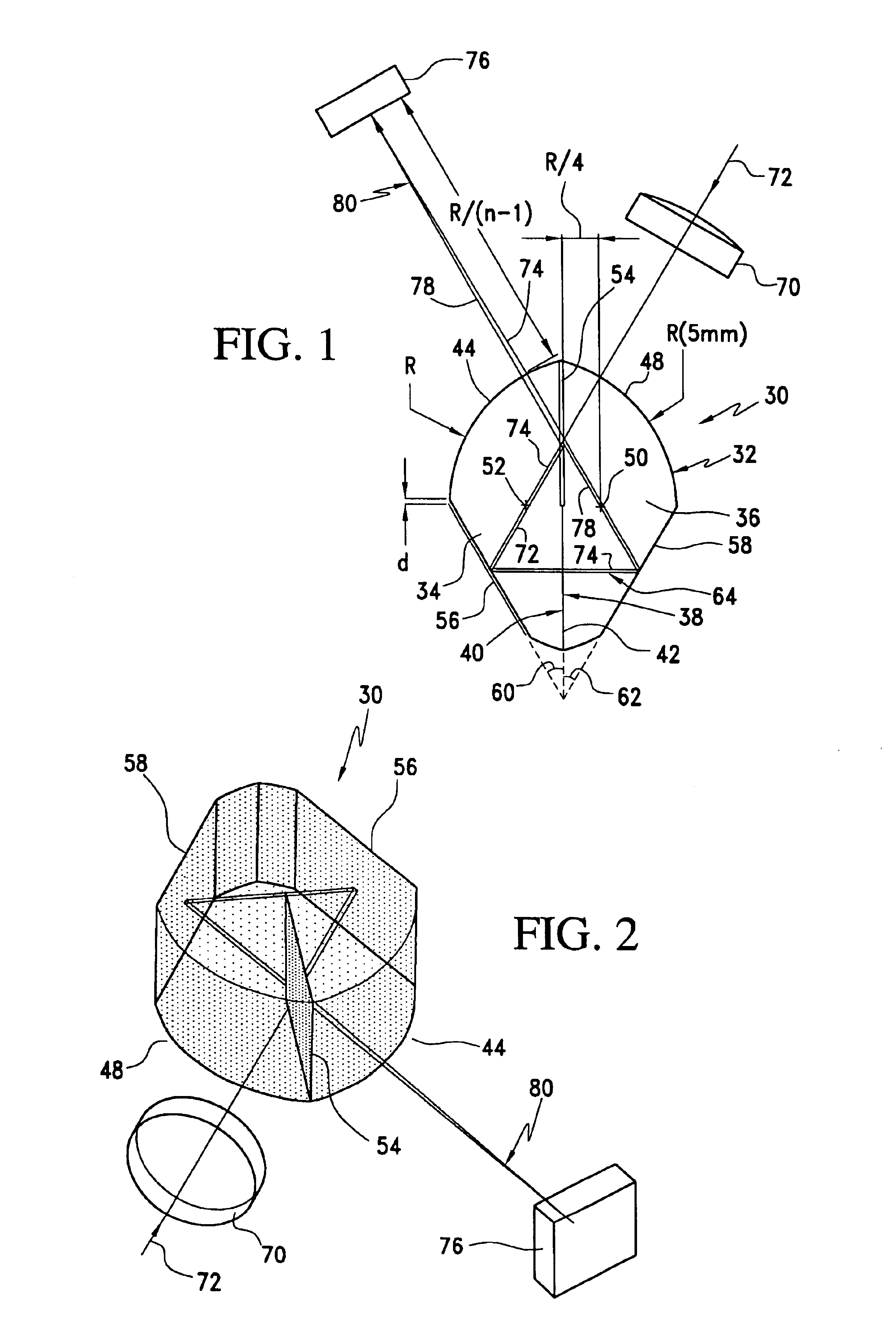
[0023]In the invention, a cylindrical HFTS 30 is illustrated by a ray tracing shown in FIG. 1 and in a three-dimensional schematic presented in FIG. 2. The interferometer 30 can be produced from a single glass rod 32 of an arbitrary radius R. The rod is cut along planes parallel to its longitudinal axis to form left and right segments 34 and 36 having respective cut surfaces 38 and 40 which are polished and assembled along line 42 to form the interferometer 30. The segments 34 and 36 incorporate respective cylindrical surfaces 44 and 48 which are portions of the rod, and the cut surfaces are located so that, when assembled, the axis 50 of cylindrical surface 44 lies in segment 36, and the axis 52 of cylindrical surface 48 lies in segment 34. Each of the axes 50 and 52 is at a distance R / 4 from the line 42 where the polished surfaces 38 and 40 are joined. Before assembly, a coating 54 is deposited on one or both of the polished surfaces 38 and 40 to form a beamsplitter which lies in ...

third embodiment

[0036]In the invention, illustrated in FIGS. 5 and 6, a simplified interferometer 200 is fabricated from standard optical components readily available from most suppliers. In this embodiment, the interferometer 200 is fabricated from two Littrow prisms 202 and 204 of BK7 glass, having surfaces formed by bases 206, 208, sides 210, 212, and hypotenuses 214, 216, respectively. A beamsplitter 220 is formed on one of the surfaces 214 or 216, and these surfaces are then glued together using an index matching glue to form the interferometer.

[0037]Surfaces 210 and 212 are coated to form mirrors, and lenses 222 and 224, also of BK7 glass, are secured to the surfaces 206 and 208, respectively. The lenses are selected so that the focal point 226 for lens 222 is located in prism 204, while the focal point 228 for lens 224 is located in prism 202, as illustrated by the ray diagram in FIG. 5. As described above, an impinging light beam 72 enters the interferometer through lens 224 and is split at...


PUM


Abstract

A digitally aberration corrected miniaturized holographic Fourier transform spectrometer (HFTS) made from simple optical components and with no moving parts is provided. The disclosed digitally aberration corrected HFTS is comprised of a two beam interferometer, which provides two interfering beams; a 2D array detector to detect the interference pattern created by the beams; a computer for correcting effects of aberrations in the pattern and calculating the spectrum from thus corrected interferogram.

Description

[0001]This application claims the benefit of U.S. Provisional application No. 60 / 428,907, filed Nov. 26, 2002, the disclosure of which is hereby incorporated herein by reference.BACKGROUND OF THE INVENTION[0002]This invention relates to the field of optical spectrometers, and more particularly to holographic Fourier transform spectrometers (HFTS), and more particularly to an aberration-limited HFTS having improved performance due to the digital aberration correction.[0003]The idea of using optical interference for retrieval of spectral information has a long history, dating back to the 19th century and works by H. Fizeau, L. Foucault and later A. A. Michelson. Rapid development of interferometric spectroscopy in the second half of the 20th century started with groundbreaking works by Fellgett and Jacquinot, who were first to document the multiplex and throughput advantages of the Fourier spectroscopic technique. By the 1960's step scan interferometers dominated the far infrared spec...

Claims


Application Information

Patent Timeline
Patent Type & Authority Patents(United States)
IPC IPC(8): G01J3/45G01J3/453
CPCG01J3/4531G01J3/4532G01J3/0259
Inventor AGLADZE, NIKOLAY I.SIEVERS, ALBERT J.
Owner CORNELL RES FOUNDATION INC
Why Eureka
Try Eureka