Continuous separator plate for use with a disk drive

a technology for separator plates and disk drives, applied in the direction of maintaining head carrier alignment, recording information storage, instruments, etc., can solve the problems of track misregistration errors (tmrs), detrimental to the performance of the disk drive, etc., to improve the air dampening characteristics, improve the shock resistance, and reduce the gap

Inactive Publication Date: 2005-08-16
WESTERN DIGITAL TECH INC
View PDF8 Cites 69 Cited by
  • Summary
  • Abstract
  • Description
  • Claims
  • Application Information

AI Technical Summary

Benefits of technology

[0002]The present invention relates to a continuous separator plate for use with a disk drive. More particularly, the present invention relates to a continuous separator plate for use with a disk drive that has improved shock resistance allowing for a smaller gap between the continuous separator plate and a rotating disk of the disk drive, which further provides for improved air dampening characteristics to aid in suppressing rotating disk and head vibration.

Problems solved by technology

One source of problems related to the performance of disk drives are track misregistration errors (TMRs).
Track misregistration errors detrimentally affect the performance of the disk drive and increase the access time to data.
Although increasing the rotational speed of the disks of the disk drive advantageously decreases access time to data, or latency times (i.e. time spent waiting for a selected data block to reach the head as a particular disk rotates), higher rotational speeds tend to induce a greater degree of turbulence in the airflow established by the rotating disks.
Such turbulence can cause unwanted vibration of the disks and the heads, leading to undesirable track misregistration errors.
Unfortunately, because of these relatively large deflections in response to a shock event, the gap between the separator plate and the rotating disk needs to be designed to be relatively large to accommodate these relatively large deflections.

Method used


Image

  • Continuous separator plate for use with a disk drive
  • Continuous separator plate for use with a disk drive
  • Continuous separator plate for use with a disk drive

Examples


Embodiment Construction

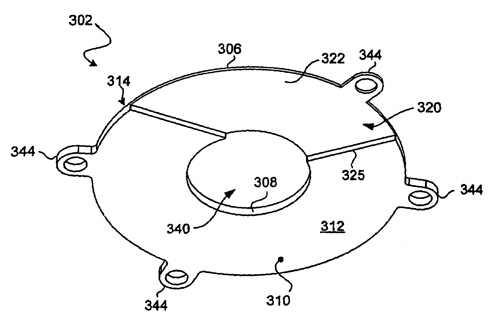
[0029]The present invention relates to a continuous separator plate for use with a disk drive. More particularly, the present invention relates to a continuous separator plate for use with a disk drive that has improved shock resistance allowing for a smaller gap between the continuous separator plate and a rotating disk of the disk drive, which further provides for improved air dampening characteristics to aid in suppressing rotating disk and head vibration.

[0030]With reference to FIG. 2, FIG. 2 is a perspective view of a hard disk drive (HDD) 100, which includes a continuous separator plate 102 that has improved shock resistance, according to one embodiment of the present invention. The disk drive 100 includes a head disk assembly (HDA) 101 and a printed circuit board assembly (PCBA) (not shown). As is known, the PCBA includes circuitry for processing signals and controlling the operations of the disk drive. The HDA 101 includes a base 116 and a separate cover 117 attached to the ...


PUM

PropertyMeasurementUnit
sizesaaaaaaaaaa
sizesaaaaaaaaaa
thickaaaaaaaaaa

Abstract

Disclosed is a continuous separator plate for use with a disk drive. The continuous separator plate includes a substantially circular continuous outer circumference and a substantially circular continuous inner circumference. A continuous radial portion may be defined between the substantially circular continuous outer and inner circumferences. The continuous radial portion is to be disposed between at least one disk of the disk drive and either the cover or the base of the disk drive, respectively. Further, the continuous radial portion includes a disk side that faces the at least one disk and an opposite side that faces either the cover or the base, respectively. The continuous separator plate further includes a head stack assembly (HSA) accommodation section to accommodate an HSA.

Description

BACKGROUND OF THE INVENTION[0001]1. Field of the Invention[0002]The present invention relates to a continuous separator plate for use with a disk drive. More particularly, the present invention relates to a continuous separator plate for use with a disk drive that has improved shock resistance allowing for a smaller gap between the continuous separator plate and a rotating disk of the disk drive, which further provides for improved air dampening characteristics to aid in suppressing rotating disk and head vibration.[0003]2. Description of the Prior Art and Related Information[0004]A huge market exists for hard disk drives for mass-market host computer systems such as servers, desktop computers, and laptop computers. To be competitive in this market, a hard disk drive should be relatively inexpensive, and should accordingly embody a design that is adapted for low-cost mass production. Further, there exists substantial competitive pressure to continually develop hard disk drives that ...

Claims


Application Information

Patent Timeline
Patent Type & Authority Patents(United States)
IPC IPC(8): G11B33/08G11B5/60
CPCG11B5/6005G11B33/08
Inventor LIN, CHEN-CHILITTLE, AARON D.
Owner WESTERN DIGITAL TECH INC
Why Eureka
Try Eureka