

Fuel cell inverter
- Summary
- Abstract
- Description
- Claims
- Application Information
AI Technical Summary
Benefits of technology
Problems solved by technology
Method used
Image

Examples
Embodiment Construction
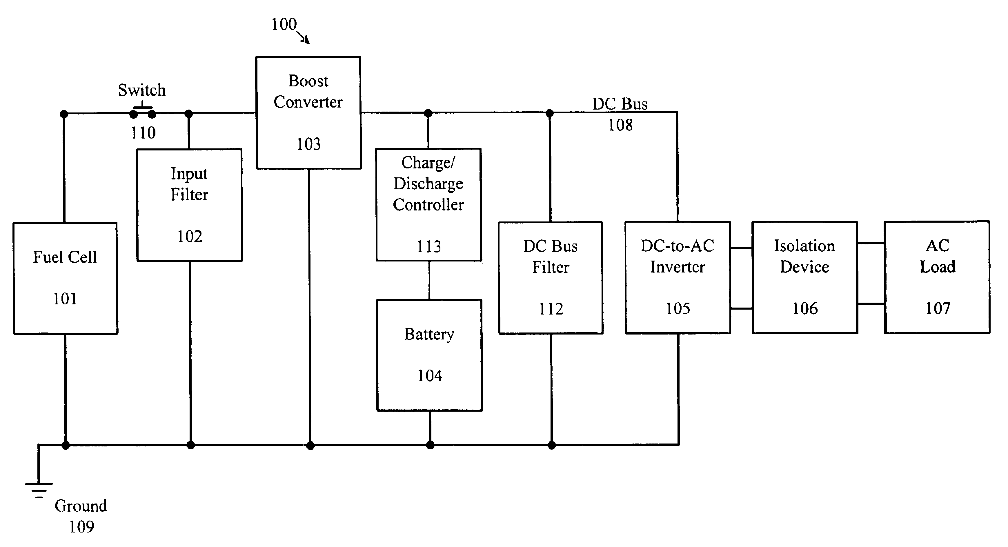
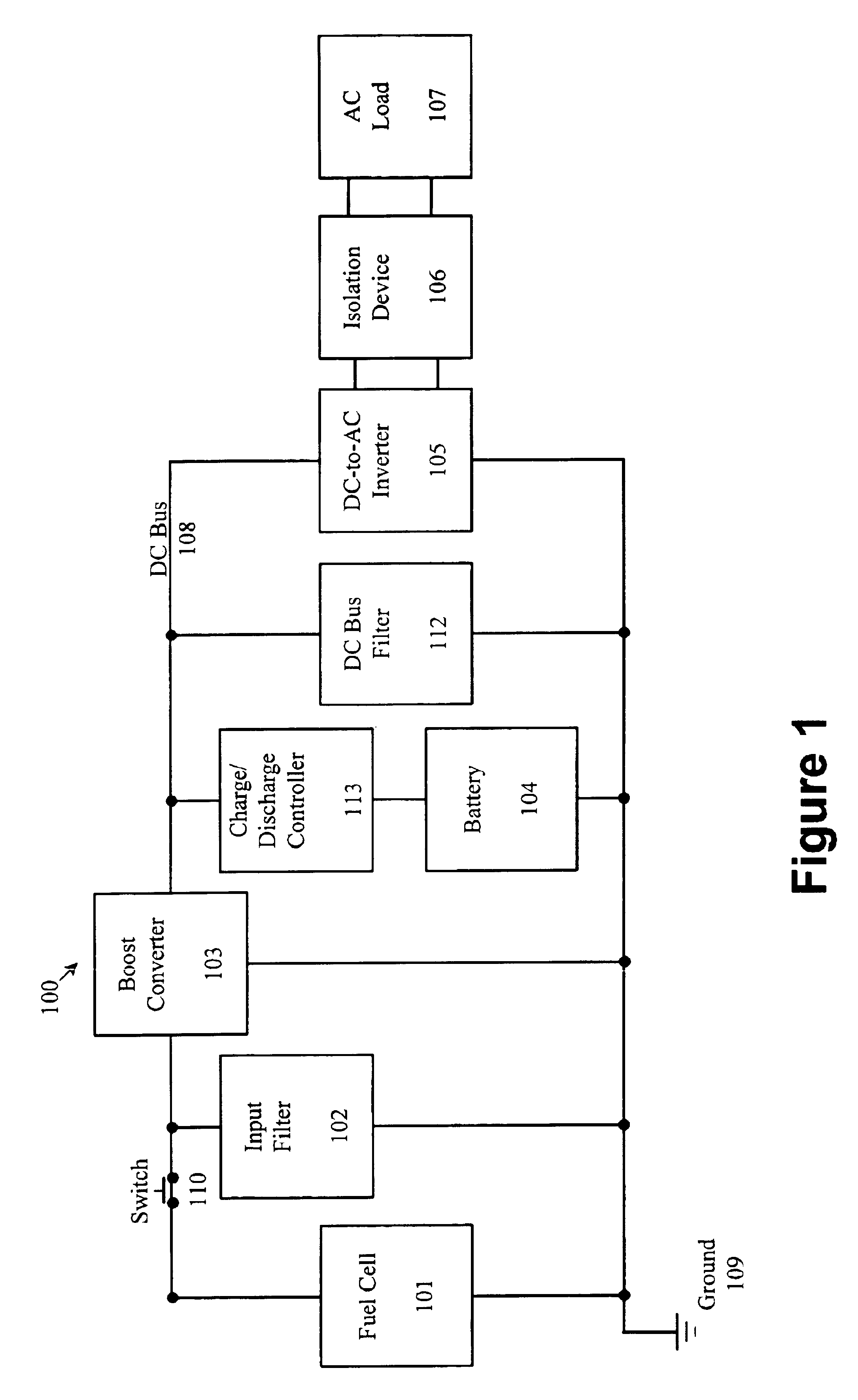
[0014]FIG. 1 provides a block diagram of a fuel cell inverter circuit 100, in accordance with the invention. As shown in FIG. 1, a fuel cell 101 is coupled to the remainder of circuit 100 via a switch 110 that operates to disconnect fuel cell 101 from the remainder of circuit 100. The input of a boost converter 103 is coupled to input filter 102 and it is also coupled to fuel cell 101 via switch 110. A charge / discharge controller 113 and a battery 104 (coupled in series to each other) are coupled to the output of boost converter 103. Battery 104 is sized to produce a voltage greater than or equal to the maximum operating voltage of fuel cell 101. A DC bus filter 112 and the input to a DC-to-AC inverter 105 are both coupled to the output side of boost converter 103. The output of boost converter 103, charge / discharge controller 113, and the input of DC-to-AC inverter 105 are coupled to a DC bus 108. DC bus 108 typically is designed to operate at voltages slightly above the voltage le...
PUM
 Abstract
Description
Claims
Application Information