Data transmitting apparatus and data transmitting method

Inactive Publication Date: 2005-08-16
PANASONIC CORP
View PDF11 Cites 7 Cited by
  • Summary
  • Abstract
  • Description
  • Claims
  • Application Information

AI Technical Summary

Benefits of technology

[0005]It is an object of the present invention to provide a data transmitting apparatus and a data transmitting method that are capable of restraining interference with other users to a minimum at the time of retransmitting transmission data.

Problems solved by technology

In the conventional data transmitting method, however, the transmission of information bits and the retransmission of parity bits are performed with the same power, causing a problem in which interference, which is equivalent to or more than interference caused at the time of transmitting information bits, will be given to other users at the time of retransmitting the parity bits.
This results in that the parity bits are retransmitted with transmission power more than necessary, thereby causing the aforementioned problem.
In this way, in a case where transmission is performed with the same power P, power per bit of parity bits becomes higher than that of information bits, increasing in a possibility that interference, which is equivalent to or more than interference caused at the time of transmitting information bits, will be given to other users at the time of retransmitting the parity bits.
Additionally, this problem occurs not only in the type II hybrid ARQ method but also in all methods in which the same power is used at the transmission data transmitting and retransmitting time.

Method used


Image

  • Data transmitting apparatus and data transmitting method
  • Data transmitting apparatus and data transmitting method
  • Data transmitting apparatus and data transmitting method

Examples


embodiment 1

[0011](Embodiment 1)

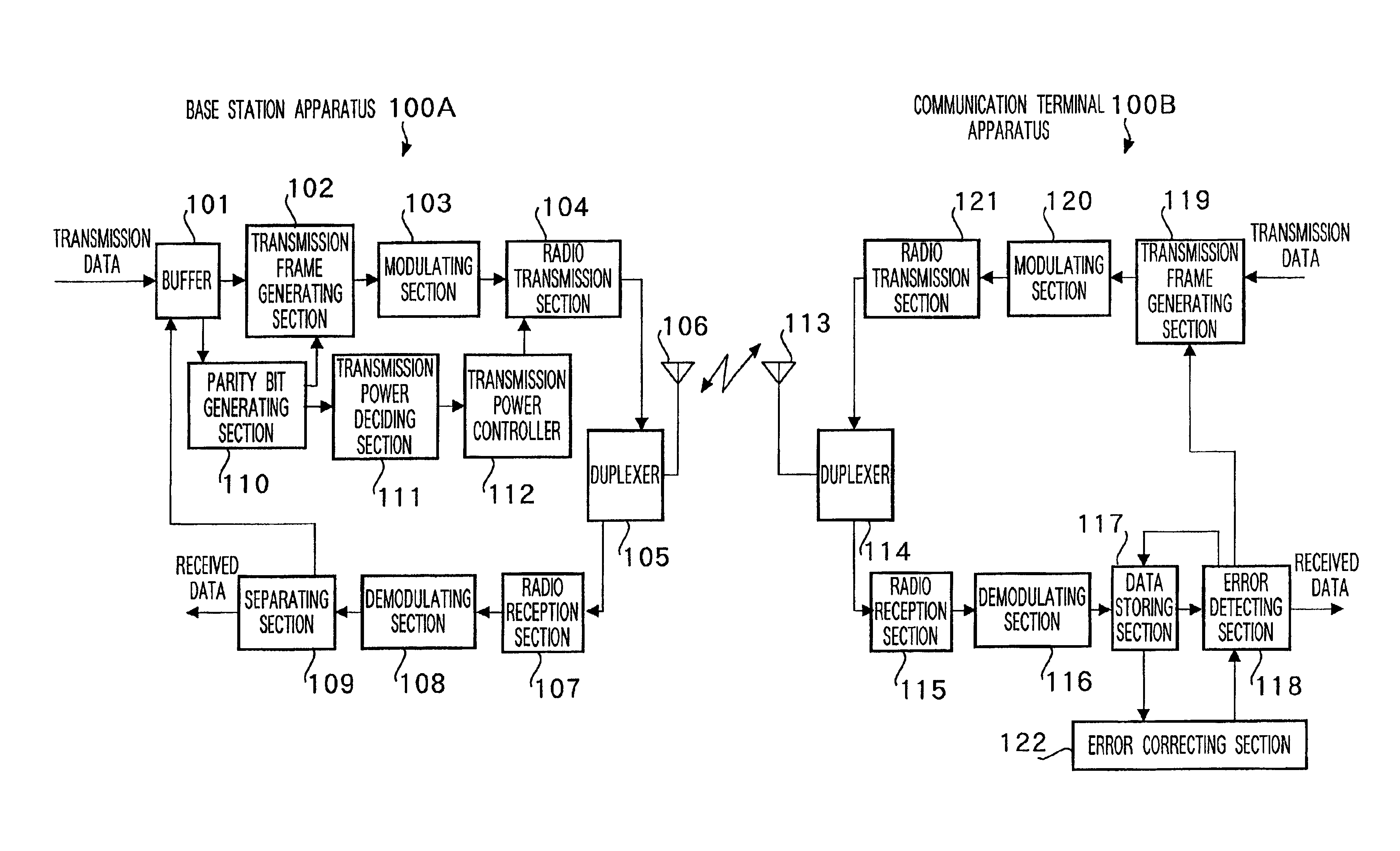
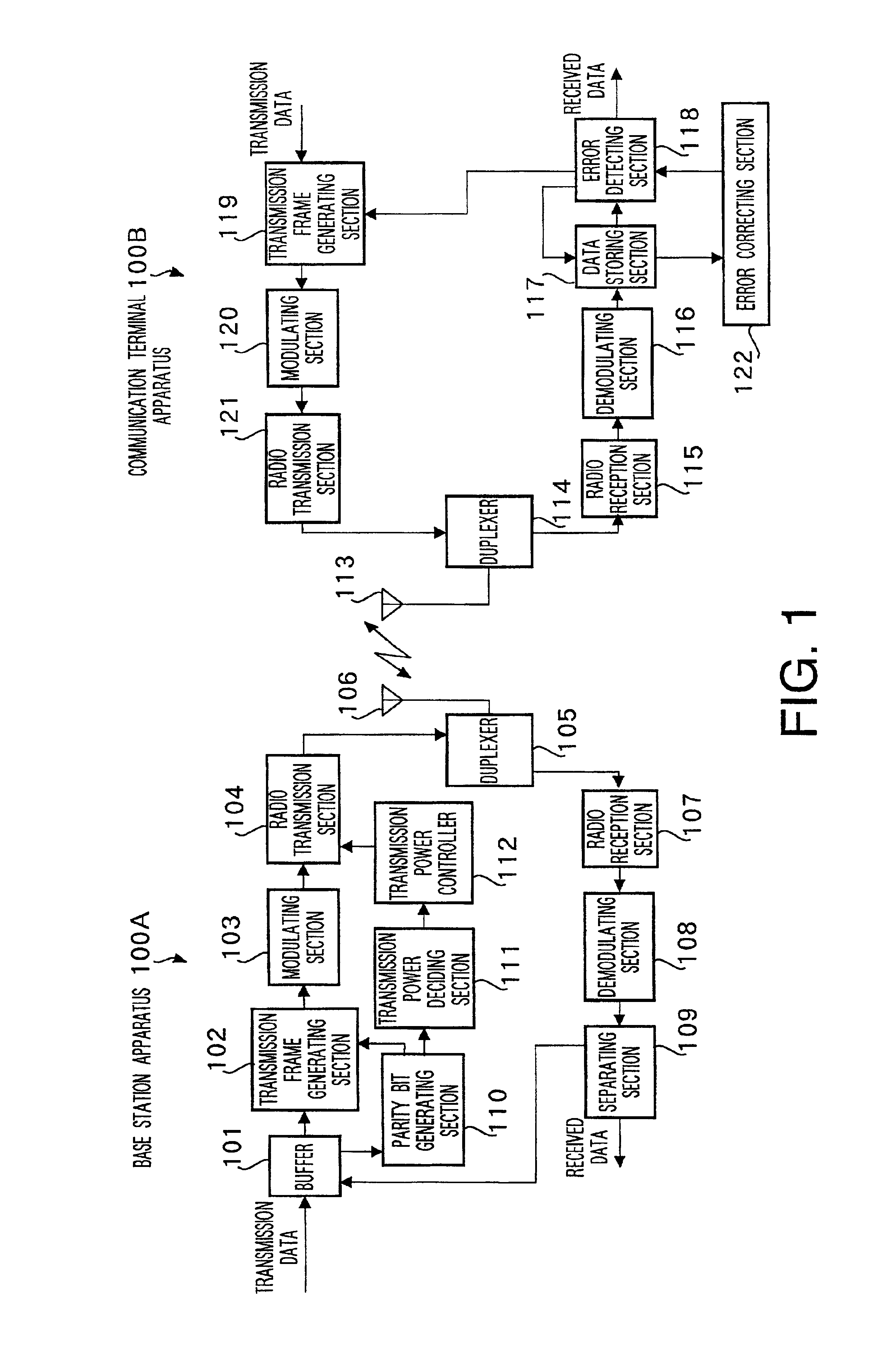
[0012]FIG. 1 is a block diagram showing each of a base station apparatus and a communication terminal apparatus according to Embodiment 1 of the present invention.

[0013]In FIG. 1, a base station apparatus 100A comprises a buffer 101 for temporarily storing transmission data, a transmission frame generating section 102 for generating a transmission frame, a modulating section 103 for modulating the transmission frame generated by the transmission frame generating section 102 so as to generate a modulated signal, a radio transmission section 104 for amplifying the modulated signal generated by the modulating section 103 up to power with a predetermined level so as to output the resultant, a duplexer 105 for assigning an antenna 106 to a transmission system or reception system, antenna 106, a radio reception section 107 for receiving a radio signal captured by the antenna 106 so as to output a modulated signal, a demodulating section 108 for demodulating the demodul...

embodiment 2

[0028](Embodiment 2)

[0029]FIG. 3 is a block diagram showing each of a base station apparatus and a communication terminal apparatus according to Embodiment 2 of the present invention. In this figure, parts identical to those in FIG. 1 are assigned the same codes as in FIG. 1 and their detailed explanations are omitted.

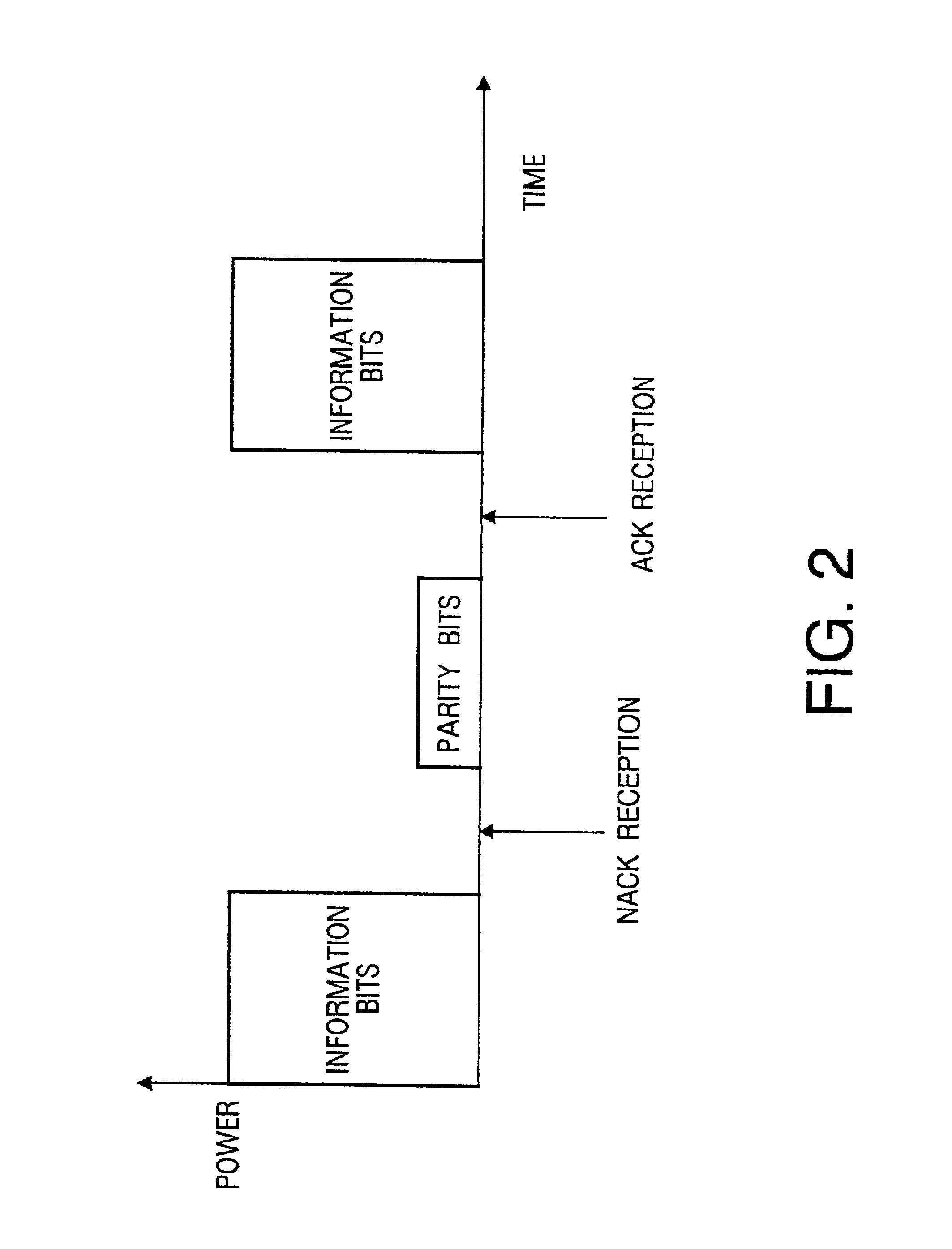
[0030]Though the aforementioned Embodiment 1 decides the power ratio between transmission data and parity bits, as a transmission power deciding method at the time of retransmitting the parity bits of FEC, based on the ratio between the number of information bits of transmission data and that of parity bits, Embodiment 2 decides it based on reception quality information in addition to the ratio between the number of information bits of transmission data and that of parity bits.

[0031]In a communication terminal apparatus 100C, a modulated signal received by the radio reception section 115 is demodulated by the demodulating section 116 and reception quality is measured b...


PUM


Abstract

A parity bit generating section 110 generates parity bits of FEC for error correction from transmission data. A transmission power deciding section 111 decides transmission power at the time of retransmitting the parity bits from the number of information bits of transmission data and the number of parity bits. A transmission power controller 112 controls transmission power based on information decided by the transmission power deciding section 111 and outputs the resultant to a radio transmission section 104.

Description

TECHNICAL FIELD[0001]The present invention relates to a data transmitting apparatus and a data transmitting method suitable for use in a communication terminal apparatus and a base station apparatus of a mobile communication system.BACKGROUND ART[0002]As an error correcting method in data transmission, for example, there is a method called a type II hybrid ARQ method (Shuichi Sasaoka: Mobile Communications, page 240, Ohmsha,Ltd). In this error correcting method, only information bits are first transmitted, and then when it is necessary to perform retransmission with respect to the transmission (namely, when a receiving side cannot demodulate the information bits correctly), only parity bits (redundant bits) of FEC (Forward Error Correction) for error correction are retransmitted. The receiving side performs error correction using information bits previously received and the parity bits that have just received.[0003]In the conventional data transmitting method, however, the transmiss...

Claims


Application Information

Patent Timeline
IPC IPC(8): H04L1/16H04B7/005H04L1/18H04L1/00H04B1/04H04B7/26H04L1/20H04L29/08
CPCH04L1/1819H04W52/20H04W52/265H04W52/54H04L1/0001
Inventor AIZAWA, JUNICHIHIRAMATSU, KATSUHIKOMIYOSHI, KENICHI
Owner PANASONIC CORP
Why Eureka
Try Eureka