Side-hole cane waveguide sensor

a waveguide sensor and cane technology, applied in the field of birefringent cane sensors, can solve the problems of limited sensitivity of birefringent sensors, difficult deformation, and limited sensitivity of fiber optic based birefringent sensors

Inactive Publication Date: 2005-08-16
WEATHERFORD TECH HLDG LLC
View PDF18 Cites 42 Cited by
  • Summary
  • Abstract
  • Description
  • Claims
  • Application Information

AI Technical Summary

Benefits of technology

[0009]The foregoing and other objects, features, and advantages of the present disclosure will become more apparent in light of the following detailed description of exemplary embodiments thereof.

Problems solved by technology

However, because optical fibers are made of glass, and are typically fragile and small, they are relatively difficult to deform, which limits the sensitivity of such sensors.
However, fiber optic based birefringent sensors are limited by their physical characteristics and manufacturing difficulties.
Additionally, fibers are small and delicate, and require special care during handling and manufacturing.
Additionally, the protective buffer coating typically formed on standard optic cable has to be contented during manufacturing as one skilled in the art will understand, which adds manufacturing complexity and hence extra time and cost.
Manufacturing yields for standard fiber-based sensors containing gratings can be lower than 10%, which is clearly not optimal.
Formation of the side-holes in the relatively small cladding of the fiber can also be difficult to accomplish.
However, cane is thicker and sturdier than fiber because of the substantial amount of cladding.

Method used


Image

  • Side-hole cane waveguide sensor
  • Side-hole cane waveguide sensor
  • Side-hole cane waveguide sensor

Examples


Embodiment Construction

[0020]In the disclosure that follows, in the interest of clarity, not all features of actual commercial implementations of a side-hole cane sensor and related techniques are described. It will of course be appreciated that in the development of any such actual implementation, as in any such project, numerous engineering and design decisions must be made to achieve the developers' specific goals, e.g., compliance with mechanical and business related constraints, which will vary from one implementation to another. While attention must necessarily be paid to proper engineering and design practices for the environment in question, it should be appreciated that development of a side-hole cane sensor and related techniques would nevertheless be a routine undertaking for those of skill in the art given the details provided by this disclosure, even if such development efforts are complex and time-consuming.

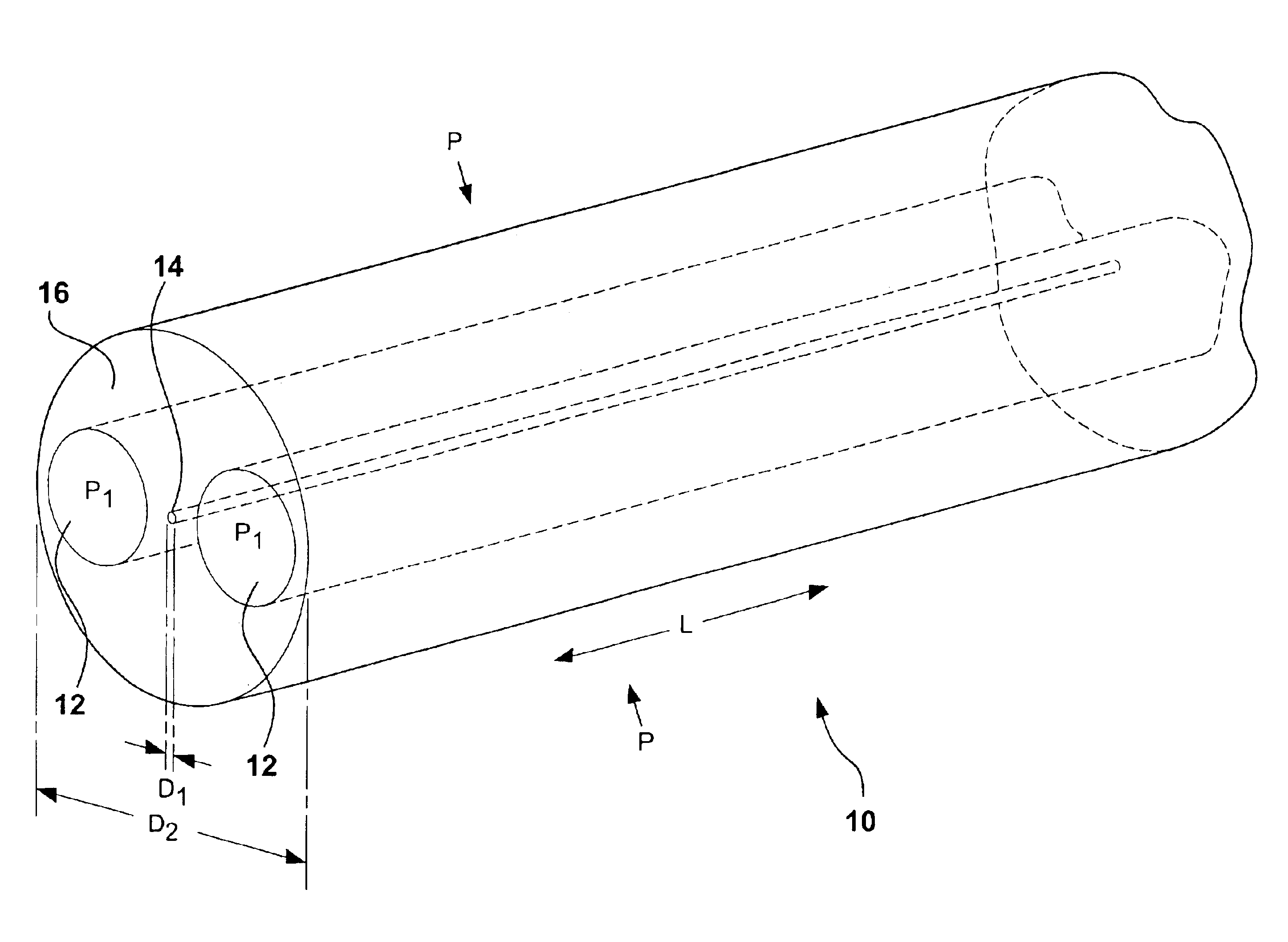
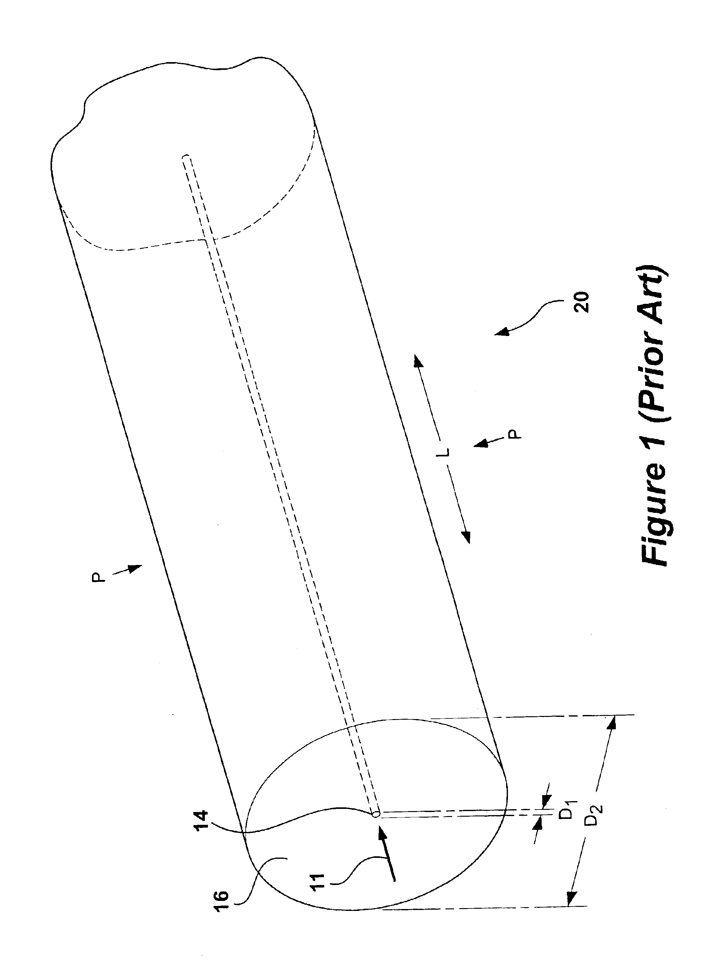
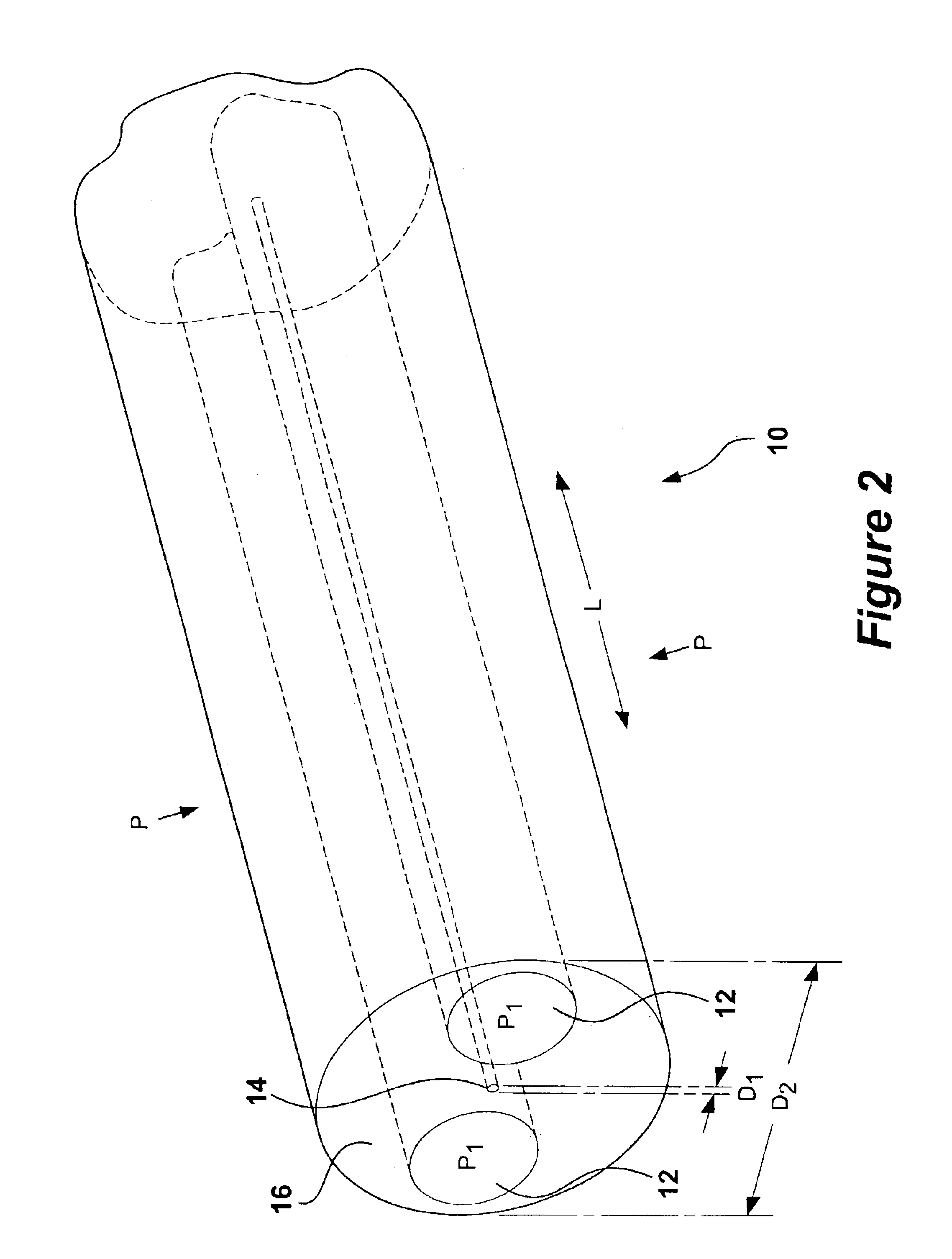
[0021]Referring to FIG. 1, a large diameter “cane” optical waveguide 20 has at least ...


PUM

PropertyMeasurementUnit
outer diameteraaaaaaaaaa
diameteraaaaaaaaaa
outer diametersaaaaaaaaaa

Abstract

A side-hole optical cane for measuring pressure and/or temperature is disclosed. The side-hole cane has a light guiding core containing a sensor and a cladding containing symmetrical side-holes extending substantially parallel to the core. The side-holes cause an asymmetric stress across the core of the sensor creating a birefringent sensor. The sensor, preferably a Bragg grating, reflects a first and second wavelength each associated with orthogonal polarization vectors, wherein the degree of separation between the two is proportional to the pressure exerted on the core. The side-hole cane structure self-compensates and is insensitive to temperature variations when used as a pressure sensor, because temperature induces an equal shift in both the first and second wavelengths. Furthermore, the magnitude of these shifts can be monitored to deduce temperature, hence providing the side-hole cane additional temperature sensing capability that is unaffected by pressure. Additionally, the side-hole cane can be used to measure a differential pressure between a first pressure ported to the side-holes and a second external pressure.

Description

CROSS-REFERENCES TO RELATED APPLICATIONS[0001]This application contains subject matter related to PCT Publication No. WO01 / 40835, published Jun. 7, 2001, publishing PCT Application No. PCT / US00 / 32934, entitled “Large Diameter Optical Waveguide, Grating, and Laser,” filed Dec. 5, 2000, which claims priority to U.S. patent application Ser. No. 09 / 455,868, filed Dec. 6, 1999, which are incorporated herein by reference in their entirety.TECHNICAL FIELD[0002]This invention relates generally to birefringent cane sensors, and more particularly, to a birefringent cane sensor having symmetrical side-holes for pressure and temperature sensing.BACKGROUND ART[0003]Birefringent optical fibers for sensing parameters such as pressure are known in the art. In a birefringent fiber, birefringence is caused in part by the geometrical asymmetry that occurs when the optical fiber deforms under strain. However, because optical fibers are made of glass, and are typically fragile and small, they are relati...

Claims


Application Information

Patent Timeline
Patent Type & Authority Patents(United States)
IPC IPC(8): E21B47/12G01L1/24G01L11/02G02B6/02G02B6/024G02B6/26
CPCG01L1/245G01L11/025G02B6/021G02B6/022G02B6/024G02B6/262E21B47/135G01L1/242G01L1/246G02B6/02314G02B6/02338G02B6/028G02B6/0281
Inventor KERSEY, ALAN D.MAIDA, JOHN L.
Owner WEATHERFORD TECH HLDG LLC
Why Eureka
Try Eureka