User interface and system for creating function block diagrams

a user interface and function block technology, applied in the field of industrial control systems, can solve the problems of not allowing the user to provide feedback loop identification, conventional configuration tools provide limited intelligence in interfacing with users, and do not provide for ensuring proper data flow in function block diagrams. to achieve the effect of accurately reflecting the function block diagram

Inactive Publication Date: 2005-08-16
ROCKWELL TECH
View PDF14 Cites 111 Cited by
  • Summary
  • Abstract
  • Description
  • Claims
  • Application Information

AI Technical Summary

Benefits of technology

[0013]In addition, the invention allows the user to reconfigure the sheet layout properties, such as for printing to a particular printer or paper size / configuration (e.g., portrait versus landscape), without losing function block information, and while ensuring that the printout accurately reflects the function block diagram. Thus, the user may move the sheet boundary from a first sheet location covering a first sheet area to a second sheet location covering a second sheet area in the user interface. The user interface may automatically move the image boundary from a first image location within the first sheet location to a second image location within the second sheet location.
[0014]In addition, where a first set of function block diagram elements are located within the first sheet area and outside the second sheet area, the user interface may automatically relocate the first set of function block diagram elements to be within the second sheet area. The user interface may maintain associations between the function block diagram elements in the function block diagram in relocating the first set of function block diagram elements. This ensures that a printout employing the new sheet layout will include all the function block elements. In addition, the user interface may save the locations of the function block diagram elements before and after the relocation, so as to reconstruct the original locations if the user subsequently resets the sheet layout.

Problems solved by technology

For instance, many existing configuration tools do not provide for ensuring proper data flow in function block diagrams, instead relying on the user to perform manual function block execution ordering.
Such systems do not allow the user to provide for feedback loop identification.
In addition, conventional configuration tools provide limited intelligence in interfacing with a user, wherein the user is not made aware of logical or semantic problems in a function block diagram until a compiler or verification error is provided.

Method used


Image

  • User interface and system for creating function block diagrams
  • User interface and system for creating function block diagrams
  • User interface and system for creating function block diagrams

Examples


Embodiment Construction

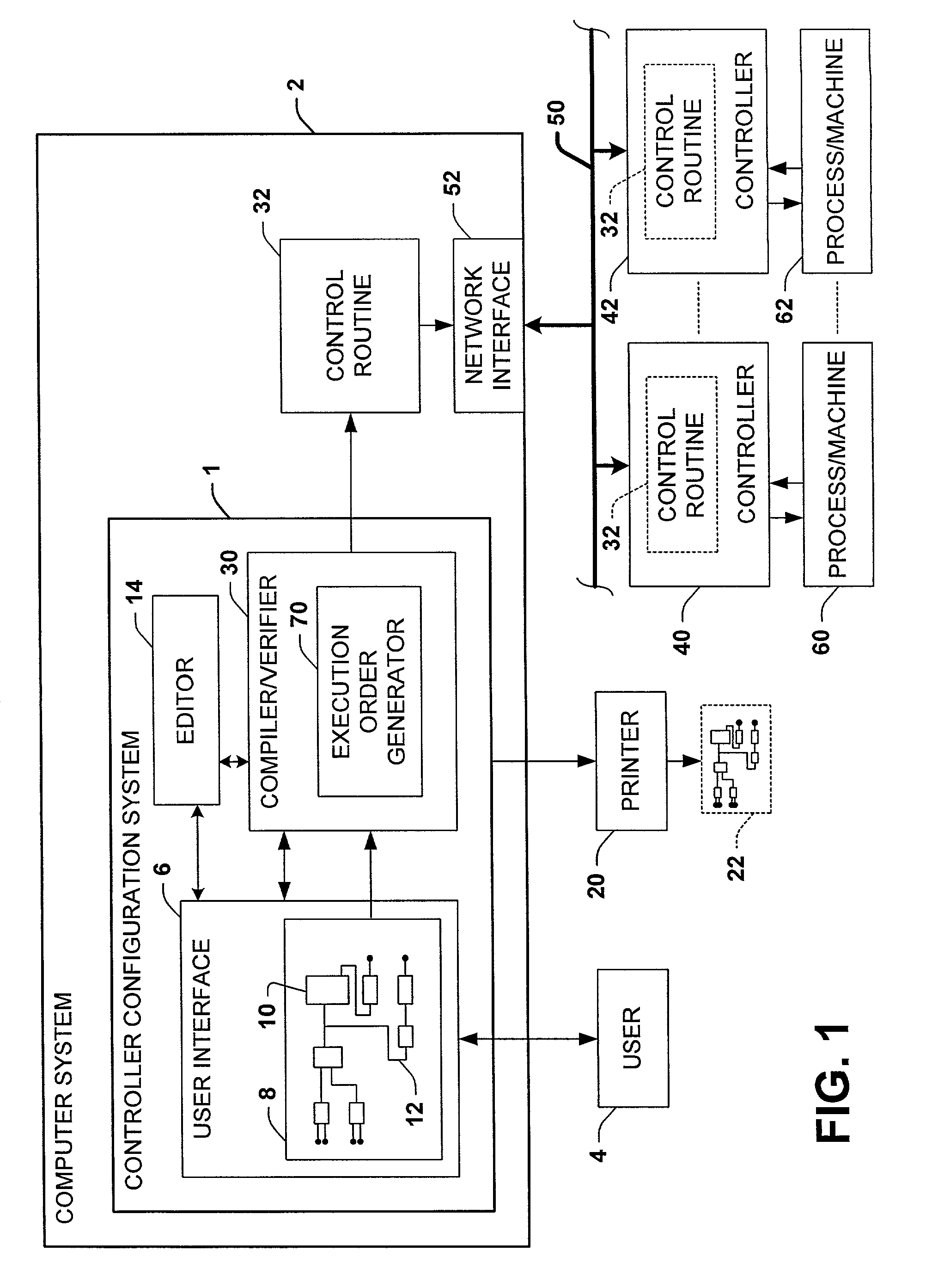
[0039]The various aspects of the present invention will now be described with reference to the drawings, wherein like reference numerals are used to refer to like elements throughout. The invention provides a controller configuration system and a user interface therefor, which allow a user to easily create and edit function block diagrams for use in association with a control system. In order to provide context for the various features and aspects of the invention, a brief description of an exemplary controller configuration system and user interface are hereinafter provided. It will be appreciated that one or more aspects of the invention may be carried out in association with the controller configuration systems and interfaces illustrated herein, as well as with other systems and interfaces not illustrated.

[0040]Referring now to FIG. 1, an exemplary controller configuration tool or system 1 is illustrated, which may be implemented in software, hardware, and / or combinations thereof...


PUM


Abstract

A controller configuration system and user interface therefor are disclosed for creating and editing controller function block diagrams for use in control systems. The interface provides feedback loop identification features, wire connection cross-referencing and hyperlinks, wire connector name matching, pin datatype visualization, correct wiring indication and wiring error indications, and intelligent deletion and restoration features. In addition, the interface provides block morphing, free-form text boxes, error navigation, error indication, and block execution status information.

Description

TECHNICAL FIELD[0001]The present invention relates to the art of industrial control systems, and more particularly to a user interface and method for creating function block diagrams for industrial control systems.BACKGROUND OF THE INVENTION[0002]Industrial controllers are special purpose processing devices used for controlling industrial processes, machines, manufacturing equipment, and other factory automation applications. In accordance with a control program or routine, an industrial controller may measure one or more process variables or inputs representative of the status of a controlled process, and change outputs effecting control of the process. The inputs and outputs may be binary, (e.g., on or off), and / or analog assuming a continuous range of values. The control routine may be executed in a series of execution cycles with batch processing capabilities, and may comprise one or more functional units. Such a control routine may be created in a controller configuration syste...

Claims


Application Information

Patent Timeline
Patent Type & Authority Patents(United States)
IPC IPC(8): G05B19/42G05B19/042
CPCG05B19/0426G05B2219/23167G05B2219/23258G05B2219/23278
Inventor LEE, JASON M.REICHARD, DOUGLAS J.HEINEKING, UNNI M.CHRISTENSEN, BRUCE A.JOHNSON, HOLLY E.HOGAN, KEITH M.SKIPPERS, KIM L.RITCHIE, DIANE N.ZUPONCIC, STEVEN A.JARRETT, JAMES H.STANEK, CHRISTOPHER E.
Owner ROCKWELL TECH
Why Eureka
Try Eureka