
Connection device associated with an arm of an articulated three-dimensional measuring appliance

a technology of three-dimensional measuring and connection device, which is applied in the direction of mechanical measurement arrangement, mechanical roughness/irregularity measurement, instruments, etc., can solve the problems of appliance losing calibration, electrical connection wires becoming twisted and knotted, and it is not possible to prevent the electrical connection wire from falling or breaking, etc., to achieve a large rotation range and avoid the risk of losing calibration

Active Publication Date: 2005-08-23
HEXAGON TECH CENT GMBH
View PDF16 Cites 190 Cited by
  • Summary
  • Abstract
  • Description
  • Claims
  • Application Information

AI Technical Summary

Benefits of technology

The present invention is a connection device for an articulated three-dimensional measuring appliance that allows for a large range of rotation without losing electrical power supply or calibration. The device includes a moving assembly rigidly secured to the arm of the appliance and mounted in the tubular body of the arm to turn about the longitudinal axis of the arm. The moving assembly has first and second components on a common axis, with connection means providing an electrical link between these components. The coupling system with successive dogs allows for a large range of rotation without interfering with measurement accuracy. The device also includes a complementary indexing system that provides a hard point for accurate positioning. The first component acts as a coder shaft for measuring the rotation of the jointed end about the longitudinal axis of the arm. The second component comprises two disks on a common axis interconnected by a hollow shaft, with contact members that co-operate with contact members on the fixed assembly. The short angular range of rotation is about 20° to -30°. The electrical connection wires are connected to the coaxial tracks carried by the second component. The invention solves the problem of large range of rotation without losing accuracy and provides a compact structure.

Problems solved by technology

However, none of the solutions set out in the above-mentioned patents gives full satisfaction.
If the abutment is a rigid mechanical abutment, making contact inevitably leads to a jolt which is transmitted along the articulated structure, which inevitably leads to the appliance losing calibration.
However, in spite of the improved security that is thus obtained, it is not possible to prevent the electrical connection wires becoming twisted and knotted or breaking.
This means that the various abutment systems that might be envisaged are considered as being not being very satisfactory.
However, that type of arrangement is not completely satisfactory concerning the quality of the electrical contact between the wipers and the tracks.
Consequently, it is not possible to avoid generating interference which disturbs the measurement signal.
Furthermore, the need to exert rotary torque of non-negligible level on the arm concerned also runs the risk of interfering with measurement accuracy: even a small amount of torque applied to a jointed arm of a multiple-arm measuring appliance can lead to an error of a few microns in the terminal sensor, thereby falsifying measurement to a greater or lesser extent.

Method used


Image

  • Connection device associated with an arm of an articulated three-dimensional measuring appliance
  • Connection device associated with an arm of an articulated three-dimensional measuring appliance
  • Connection device associated with an arm of an articulated three-dimensional measuring appliance

Examples


Embodiment Construction

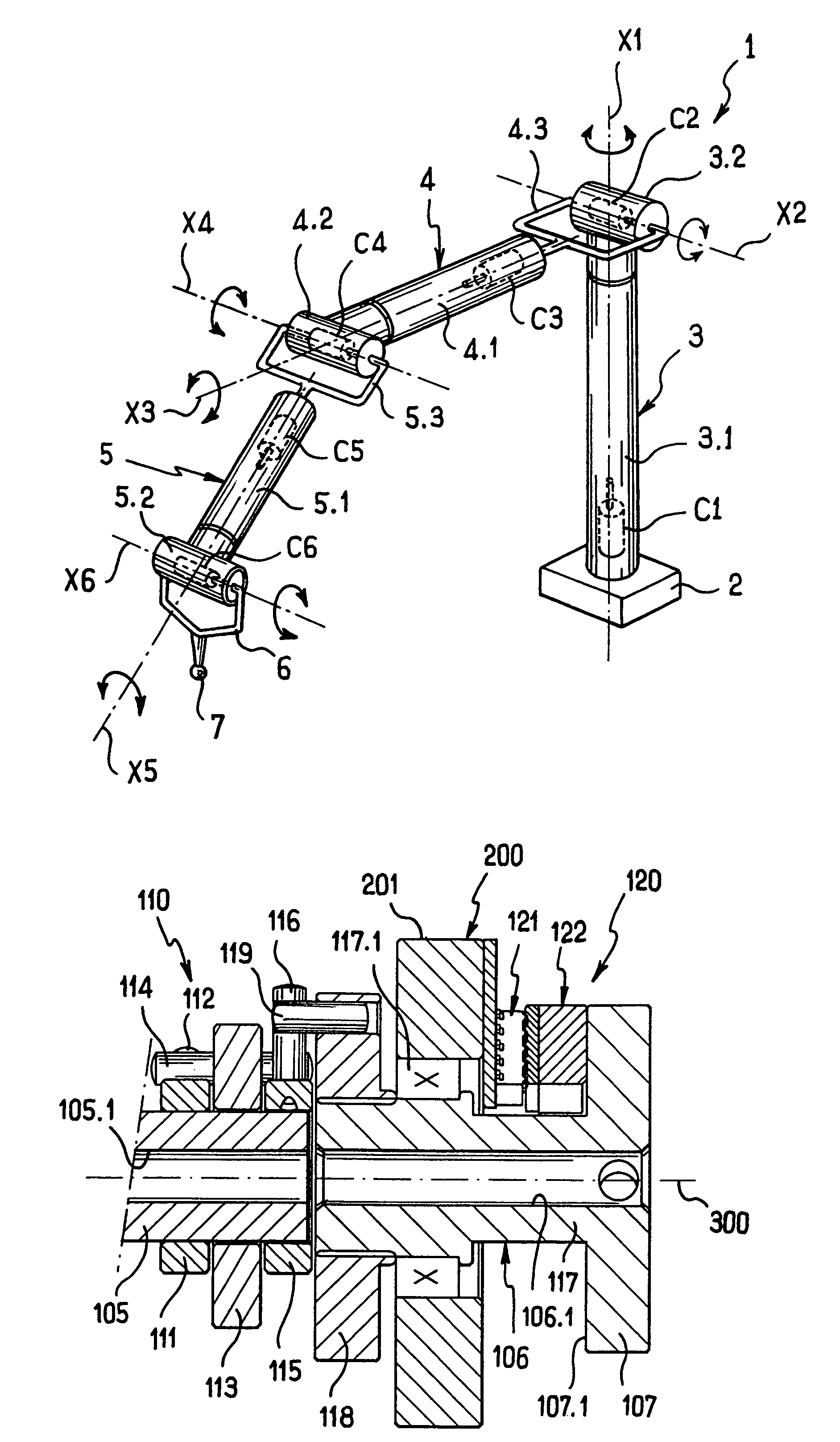
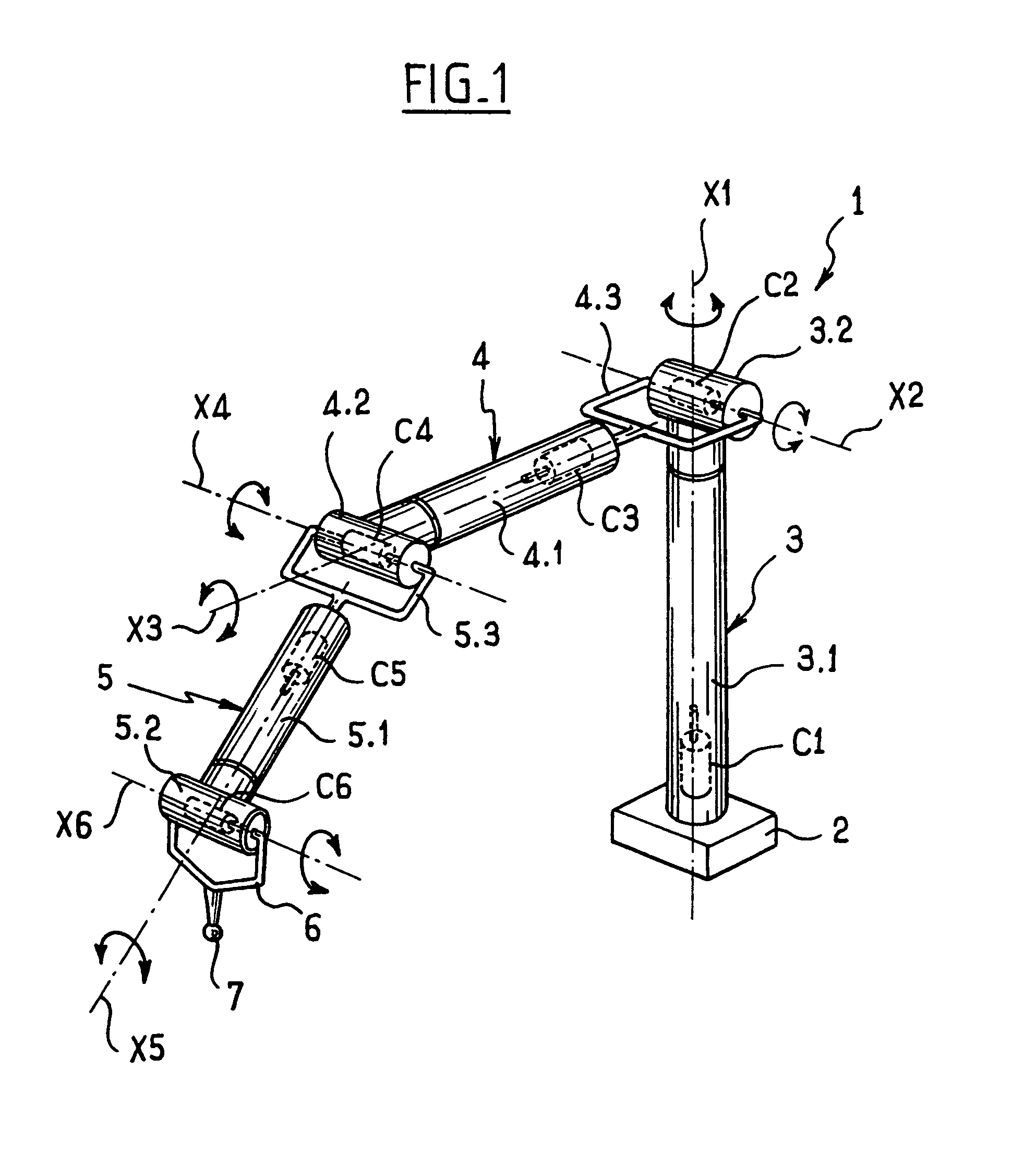
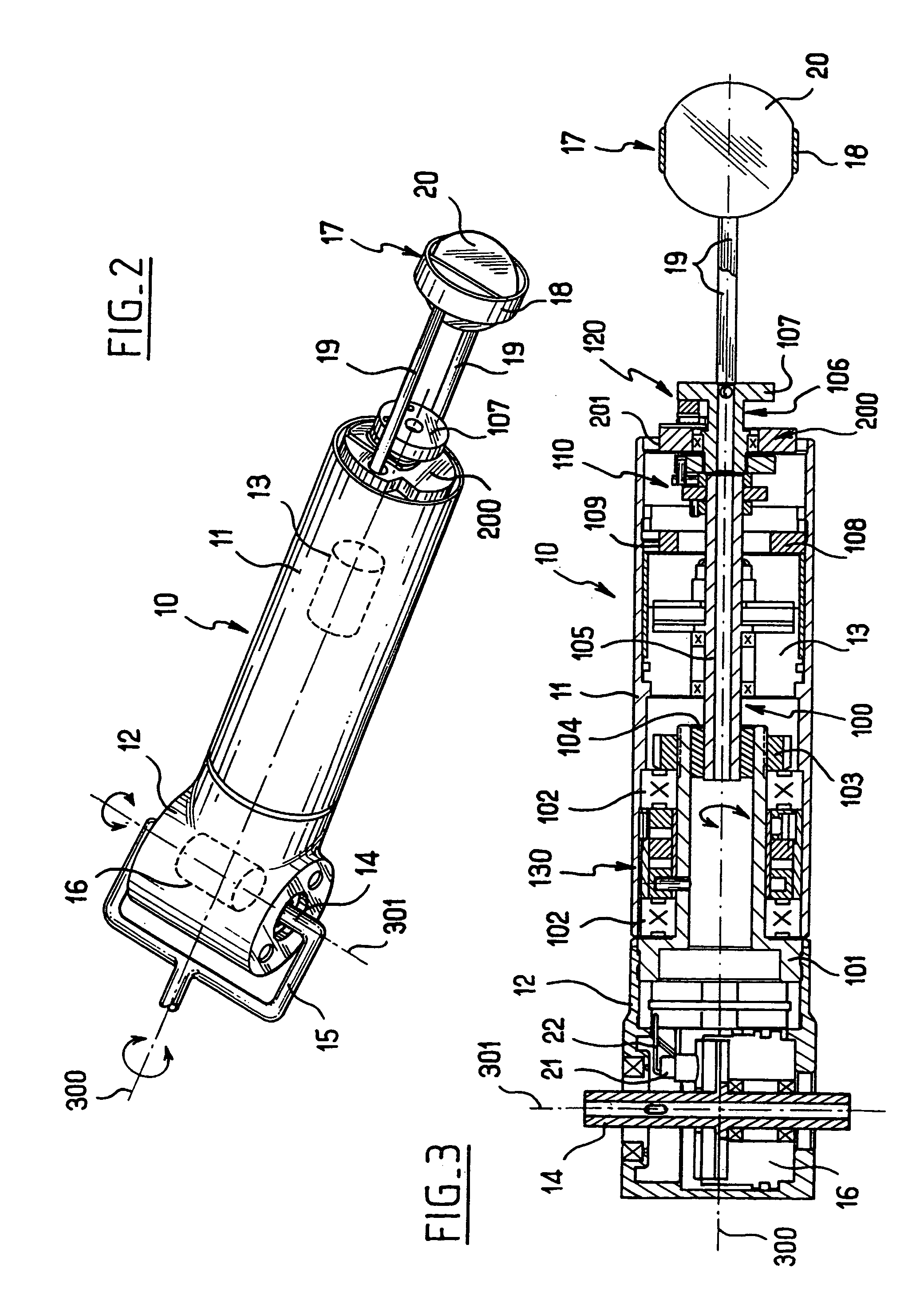
[0030]Reference is made below to FIGS. 1 to 11 to describe in greater detail the structure of an arm of an articulated three-dimensional measuring appliance fitted with a connection device in accordance with the invention.

[0031]FIG. 1 shows an articulated three-dimensional measuring appliance referenced 1 comprising specifically a support stand 2 on which a rotary first arm 3 is mounted, followed by two jointed arms 4 and 5 and a measurement sensor 7 mounted at the end of a fork-shaped jointed support 6. Such a structure for the appliance is entirely conventional in general terms.

[0032]The first arm 3 comprises a tubular body 3.1 of axis X1 terminated by a jointed end 3.2 capable of turning about the central axis X1. The jointed end 3.2 carries a pivoting fork 4.3 forming part of the following arm 4, which fork can pivot about an axis referenced X2. The following arm 4 is connected to the pivoting fork 4.3 and comprises a tubular body 4.1 and a jointed end 4.2, which end is capable ...


PUM


Abstract

The invention relates to a connection device associated with an arm of an articulated three-dimensional measuring appliance, the device comprising a moving assembly and a fixed assembly, together with connection means for providing an electrical link between said two assemblies. In accordance with the invention, the moving assembly comprises first and second adjacent components on a common axis, the first component being constrained to rotate with the jointed end of the arm and being connected to the second component by a coupling system having successive dogs so that said second component is entrained in rotation only after said first component has turned through significantly more than one revolution in the same direction, and the connection means comprise facing contact members carried respectively by the fixed assembly and by the second component, arranged to provide a continuous electrical link in normal operation and a link that is restricted to a short angular range of rotation once the second component is entrained in rotation by the first component.

Description

[0001]This application is entitled to the benefit of and incorporates by reference essential subject matter disclosed in French Patent Application No. 03 012674 filed on Oct. 29, 2003.FIELD OF THE INVENTION[0002]The present invention relates to a connection device associated with an arm of an articulated three-dimensional measuring appliance.BACKGROUND OF THE INVENTION[0003]There exist very numerous patent documents illustrating structures for articulated three-dimensional measuring appliances including a plurality of joint axes. Thus, recent measuring appliances have up to six axes.[0004]Reference can be made to documents U.S. Pat. No. 5,402,582, U.S. Pat. No. 5,611,147, U.S. Pat. No. 5,794,356, and U.S. Pat. No. 5,926,782. In general, articulated three-dimensional measuring appliances conventionally comprise a moving assembly rigidly secured to a jointed end of an arm and mounted in the tubular body of the arm to turn about the longitudinal axis of said arm, and a fixed assembly m...

Claims


Application Information

Patent Timeline
Patent Type & Authority Patents(United States)
IPC IPC(8): B25J17/00G01B21/02G01B21/20G01B21/04G01B5/28G01B7/008G01B5/008G01B7/28H01R35/00H01R39/00H01R39/08H01R35/04
CPCG01B5/008H01R35/04
Inventor GRANGER, ROMAIN
Owner HEXAGON TECH CENT GMBH
Learn More