Web structure and method for making the same
a technology of web structure and web structure, applied in the field of web structure, can solve the problems that the edges may affect the limit of fractal design, and achieve the effect of strong and stable structures, strong and stable architectural and structural support structures
- Summary
- Abstract
- Description
- Claims
- Application Information
AI Technical Summary
Benefits of technology
Problems solved by technology
Method used
Image
Examples
experiment 1
Modeling 4-web Columns
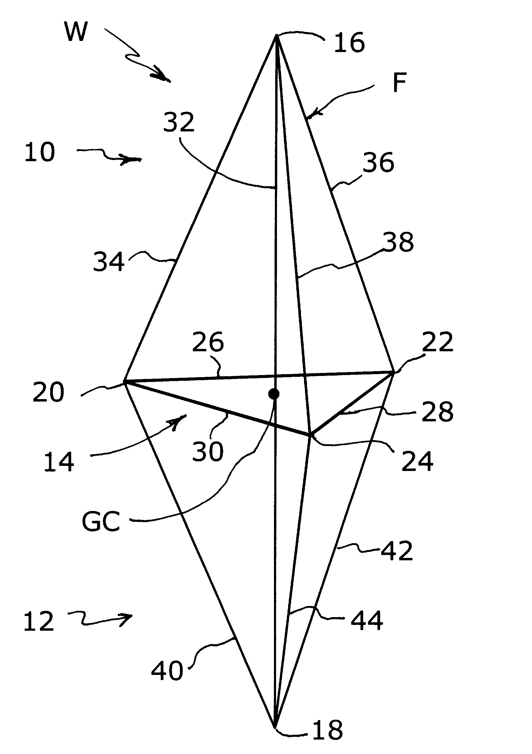
[0084]Level-0, level-1, and level-2 wafers WF (the basic building blocks) were generated via the process of specifying nodes and edges. Nodes are points in 3-space. Each such point represents the center of a joint where two or more tubes and / or solid rods would be welded together. Edges were provided as pairs of nodes. Each edge represents either a tube or solid rod. The tubes / rods are of three distinct kinds, namely, horizontal, slant, and vertical. FIG. 34 shows a level-1 4-web wafer, and FIGS. 35-36 show all of the tubes / rods that comprise a level-1 4-web wafer. In other words, the wafer components shown in FIGS. 35-36 are joined to form the wafer shown in FIG. 34. In particular, wafer component shown in FIG. 35 includes three vertical edges (or segments) 84. Three slant edges 86 stem from the bottom of the middle segment 84′. The remaining edges 88 form horizontal edges. The wafer component shown in FIG. 36 includes horizontal edges 88 and nine slant edges ...
experiment 2
Adopting and Understanding Standards
[0087]The adopted standards for all columns were (1) a cross-section that would nominally fit into a 3.5-inch by 3.5-inch square; and (2) a height of 8 feet. The goal was to compare various 4-web columns to standard 8-foot sections of A36 structural steel pipe whose outside diameter (OD) was 3.5 inches. Except for Experiment 3 (below), where it was assumed that one end was fixed and one end was free, the tests were restricted to the case where both ends of each column were fixed.
[0088]The standard 3.5-inch OD pipes, as well as the 4-web columns, can fail for one of two reasons—they can bend (buckle) or the A36 steel can fail (A36 steel will support up to 36,000 lbs per square inch.) The load C at which an A36 steel pipe will fail due to steel failure is C=A*36000 where A is the cross-sectional area (inches squared) of the pipe. The load B at which a pipe will buckle was calculated via the compressive strength equations [Reference No. 1, page 2-22]...
experiment 3
The First Computer Results
[0101]We started with several level-1 12-inch wafer columns whose members were solid rods. The assumptions underlying the first tests where that the top end of these columns where free, in all other tests the assumption was that we had both ends fixed, allowing movement only in the vertical direction.
[0102]The 12-inch level-1 wafer columns whose buckling data appear in FIG. 41 had members whose specifications are listed below in Table 1 (note that each member of the 4-web column was a solid rod).
[0103]
TABLE 1PIPEODwall thicknessweightbuckling load3.5″.25″69.3 lbs23,083 LRFDLevel-1 12-inch wafer columnsSlant / Vertical / Horizontalweightbuckling load.2 D / .4 D / .2 D53 lbs10,230.2 D / .5 D / .2 D69 lbs12,729.3 D / .4 D / .2 D79 lbs17,050.3 D / .4 D / .3 D81 lbs17,269Note: All buckling loads on 4-web columns are calculated via Mechanica.
PUM
 Abstract
Description
Claims
Application Information
 - R&D
- Intellectual Property
- Life Sciences
- Materials
- Tech Scout
- Unparalleled Data Quality
- Higher Quality Content
- 60% Fewer Hallucinations
Browse by: Latest US Patents, China's latest patents, Technical Efficacy Thesaurus, Application Domain, Technology Topic, Popular Technical Reports.
© 2025 PatSnap. All rights reserved.Legal|Privacy policy|Modern Slavery Act Transparency Statement|Sitemap|About US| Contact US: help@patsnap.com


