Method and arrangement for defrosting a vapor compression system

Inactive Publication Date: 2005-08-23
SINVENT AS
View PDF9 Cites 17 Cited by
  • Summary
  • Abstract
  • Description
  • Claims
  • Application Information

AI Technical Summary

Benefits of technology

[0005]The present invention solves the disadvantages of the aforementioned systems by providing a new, improved,

Problems solved by technology

The heat exchanger heat transfer capability and resulting system performance will be reduced due to frost buildup.
The first method (electric defrosting) is simple but not efficient, while the hot gas defrosting method is most suitable when the system has two or more evaporators.
This aspect might limit, for practical reasons, the type of heating means (energy sources) that can be used with this defrosting method (radiator system).
Yet another disa

Method used


Image

  • Method and arrangement for defrosting a vapor compression system
  • Method and arrangement for defrosting a vapor compression system
  • Method and arrangement for defrosting a vapor compression system

Examples


Embodiment Construction

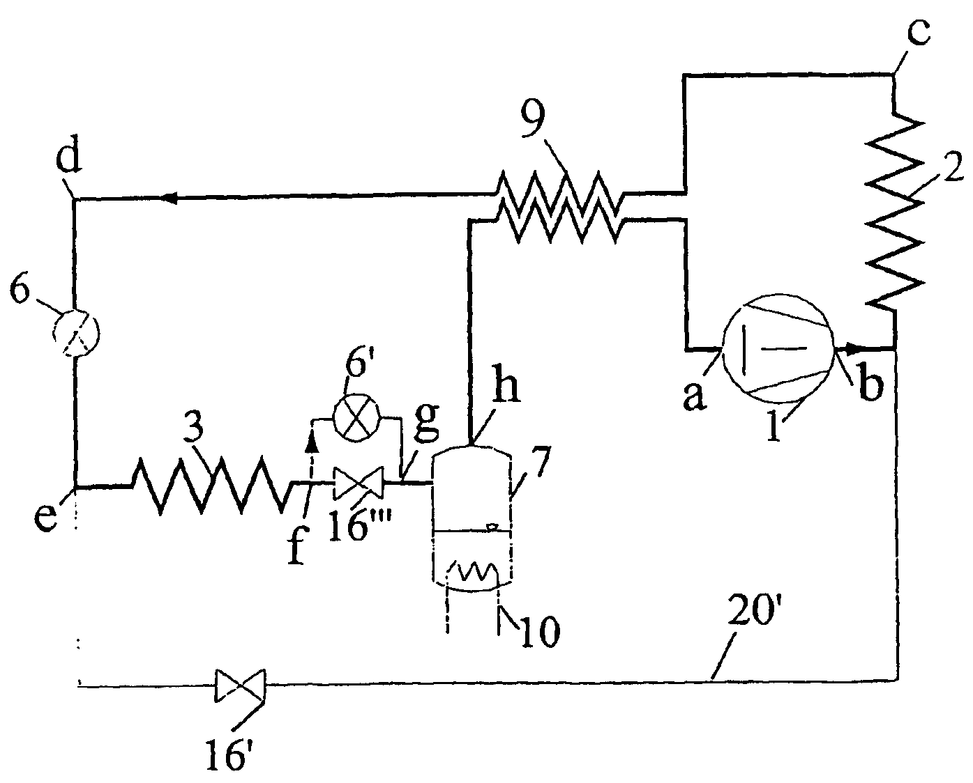
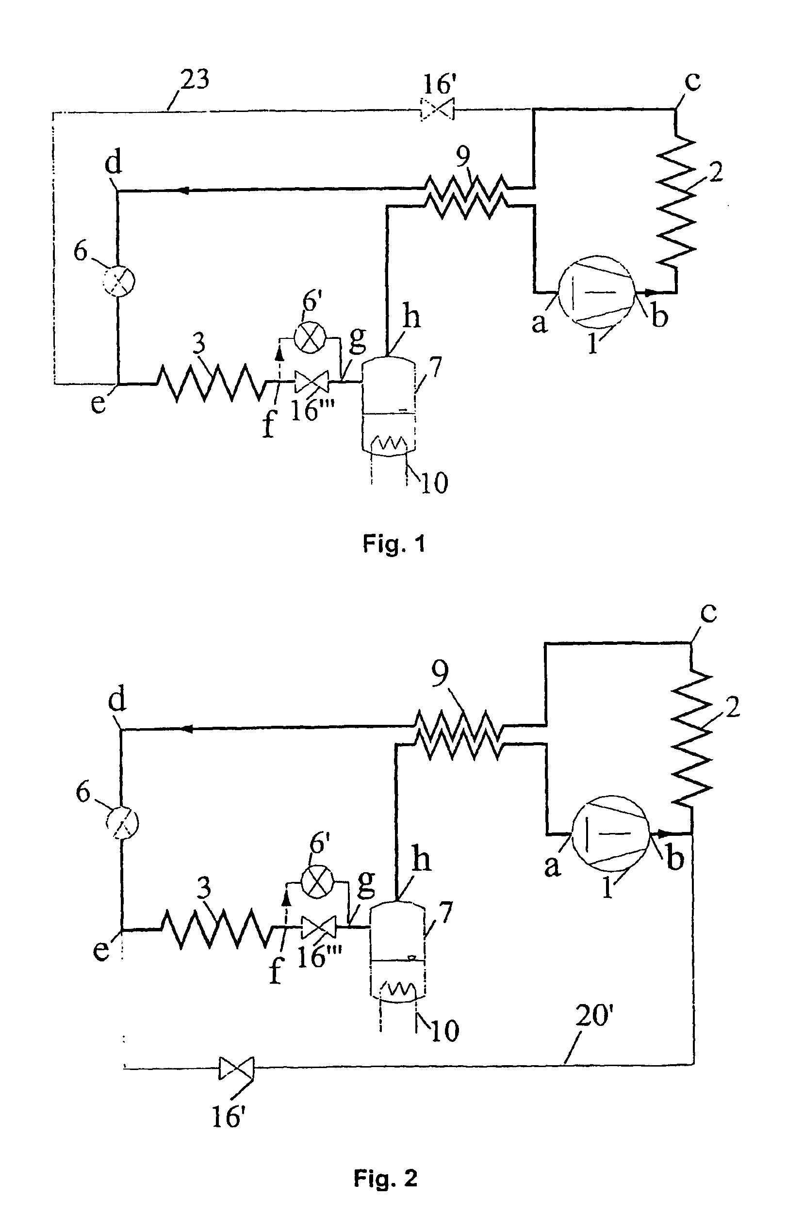
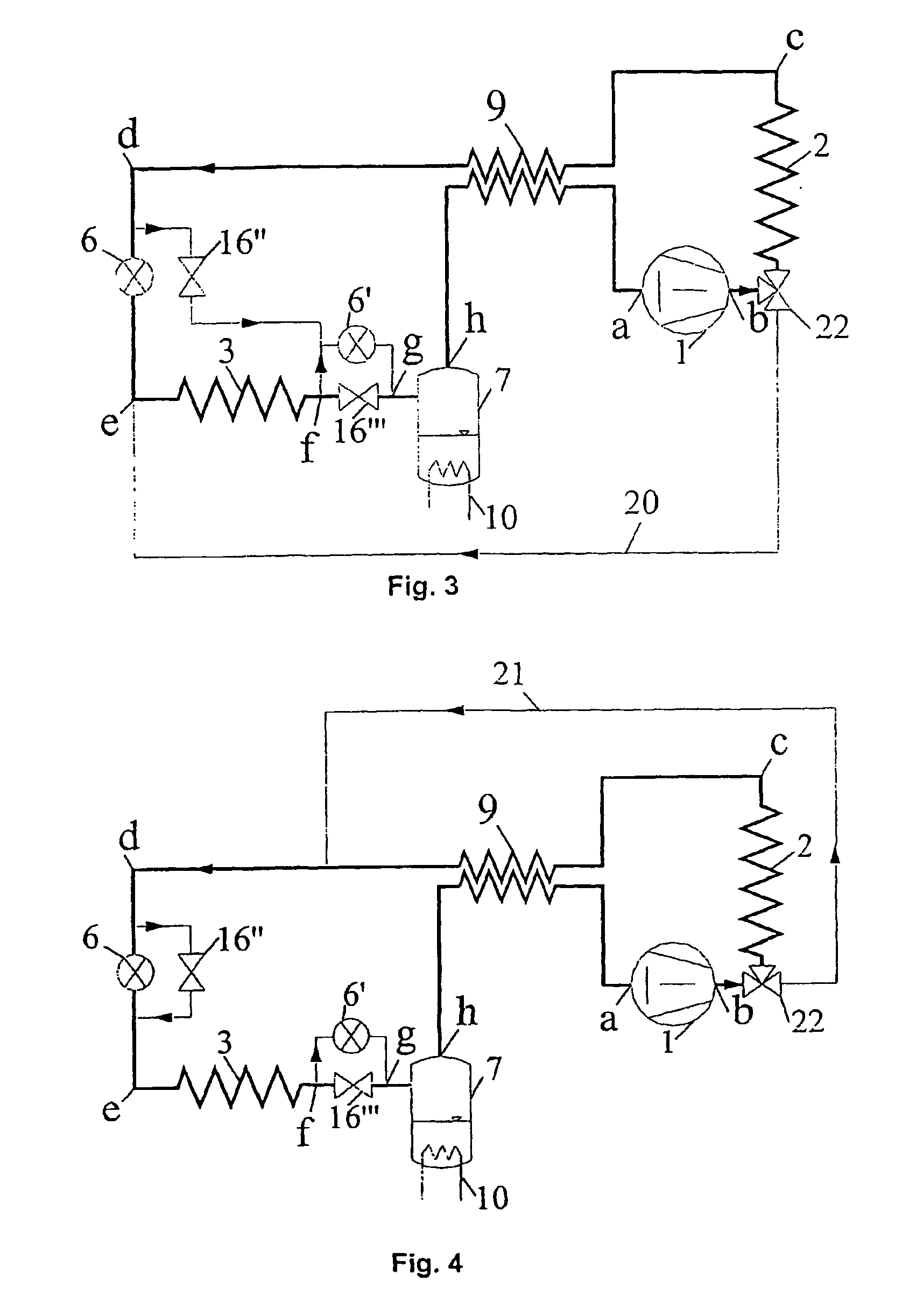
[0015]The invention relates generally to refrigeration and heat pump systems, more specifically but not limited, operating under a transcritical process, to defrost a frosted heat exchanger. In particular, the invention relates to an evaporator with any fluid as refrigerant, and in particular carbon dioxide.

[0016]The invention can be used with any refrigeration or heat pump system preferably having a pressure receiver / accumulator. If necessary, the invention can also eliminate cool interior drafts during the defrost cycle, which are associated with conventional defrosting methods in heat pump systems. This is achieved by means of an external heat source such as an electrical resistance or waste heat system (for example from a car radiator cooling system) or any other appropriate means that can be incorporated into the receiver / accumulator or connecting piping along the path of the refrigerant in the circuit. Heat can also be supplied from a storage unit. The invention can be used wi...


PUM


Abstract

A method of defrosting of a heat exchanger (evaporator) in a vapor compression system including, downstream of a heat exchanger (evaporator) (3) to be defrosted, at least a compressor (1), a second heat exchanger (condenser/heat rejecter) (2), and an expansion device (6) connected by conduits in an operable manner to form an integral closed circuit. The heat exchanger (3) to be defrosted is subjected to essentially the same pressure as the compressor's (1) discharge pressure. Thus, the heat exchanger (3) is defrosted as the high-pressure discharge gas from the compressor (1) flows through to the heat exchanger, giving off heat to the heat exchanger (3). In the circuit, in connection with the expansion device (6) a first bypass loop 23 with a first valve (16′), is provided. A pressure reducing device (6′) is provided in a second bypass loop in conjunction with a second valve (16′″) disposed downstream of the heat exchanger (3) being defrosted, whereby the first valve (16′) is open and the second valve (16′″) is closed when defrosting takes place.

Description

FIELD OF THE INVENTION[0001]The present invention relates to a method and arrangement for defrosting of the heat exchanger (evaporator) in a refrigeration or heat pump system. In addition to the first heat exchanger (evaporator), the arrangement includes at least a compressor, a second heat exchanger (heat rejecter) and an expansion device connected by conduits in an operable manner to form an integral closed circuit.DESCRIPTION OF PRIOR ART[0002]In some applications such as an air-source heat pump or air-cooler in a refrigeration system, frost will form on the heat absorbing heat exchanger (functioning as an evaporator) when the surrounding temperature is near or below the freezing point of water. The heat exchanger heat transfer capability and resulting system performance will be reduced due to frost buildup. Therefore a defrosting means is required. The most common defrosting methods are electric and hot gas defrosting. The first method (electric defrosting) is simple but not eff...

Claims


Application Information

Patent Timeline
IPC IPC(8): F25B13/00F25B9/00F25B47/02F25B40/00F25B1/10F25B1/00F25B43/00
CPCF24F3/1405F25B9/008F25B13/00F25B40/00F25B47/022F24F2003/1446F25B1/10F25B2309/061F25B2313/023F25B2400/16F25B2600/2501F25B47/02
Inventor AFLEKT, K.ANG.REBRENDENG, EINARHAFNER, ARMINNEKS.ANG., PETTERPETTERSEN, JOSTEINREKSTAD, H.ANG.VARDSKAUGEN, GEIRZAKERI, GHOLAM REZA
Owner SINVENT AS
Why Eureka
Try Eureka