Windage tray with improved captured nut

Inactive Publication Date: 2005-08-23
GENERAL FASTENERS
View PDF45 Cites 33 Cited by
  • Summary
  • Abstract
  • Description
  • Claims
  • Application Information

AI Technical Summary

Benefits of technology

[0013]In this fashion a captured nut is attached to a windage tray for an internal combustion engine or other work-piece and provides a smooth was

Problems solved by technology

A rapidly rotating crankshaft may be slowed down by excess splash of oil which may rob the engine of horsepower.
The use of separate mounting nuts to mount the windage tray on top of the upside down engine at the underside of the engine within the oil pan poses an undesirable risk.
During installation, the underside of the engine interior is exposed there is a risk that a loose nut may be dropped into the underside of the engine during installation.
If this scenario occurs, the engine may be damaged when it is turned on by the engine with its rapidly moving piston, crank arm and crank shaft banging into the loose nut.
Secondly, if after installation, the nut becomes loose and separated from the mounting bolt, the nut most likely will sink to the bottom of t

Method used


Image

  • Windage tray with improved captured nut
  • Windage tray with improved captured nut
  • Windage tray with improved captured nut

Examples


Embodiment Construction

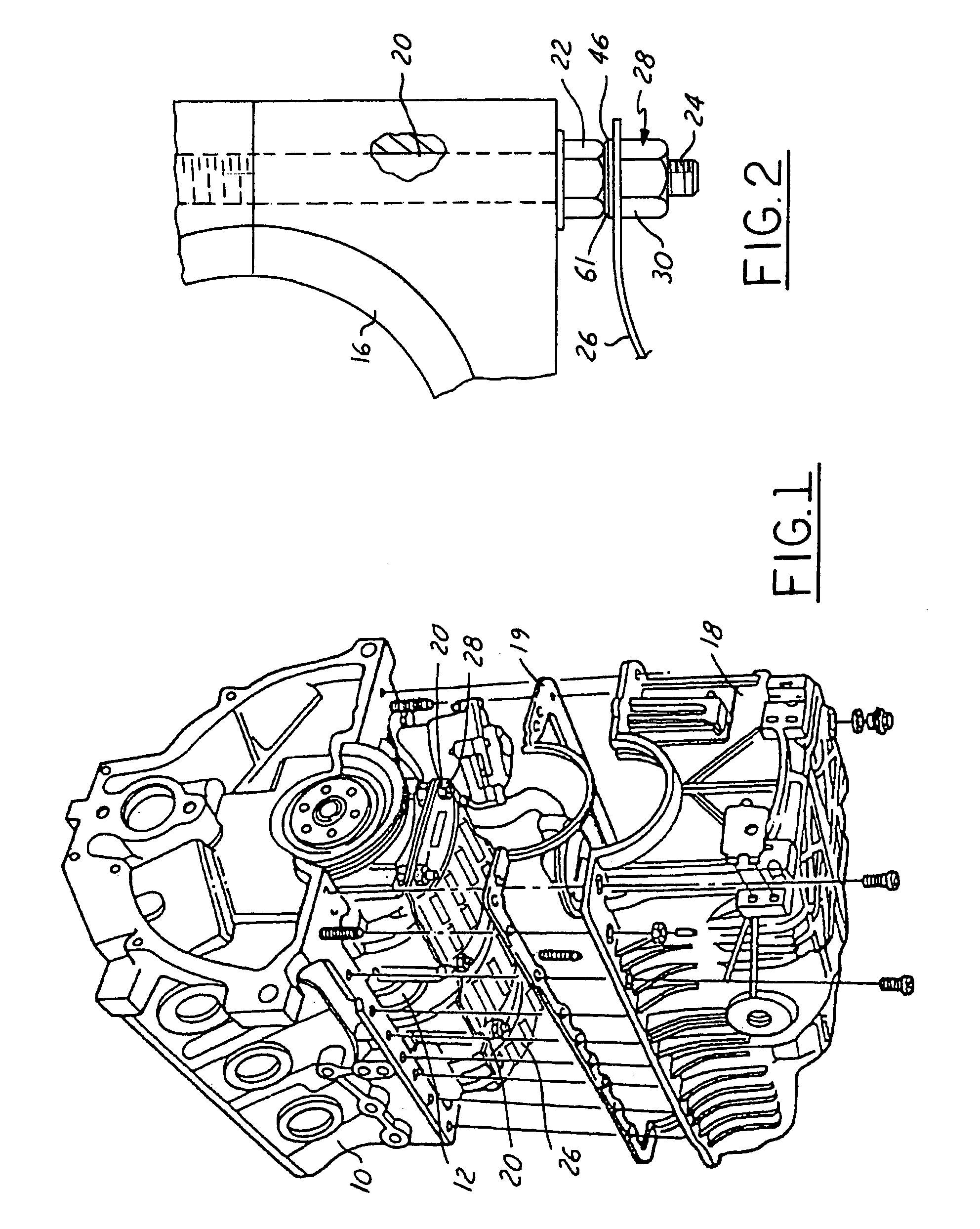
[0022]Referring now to FIGS. 1 and 2, an internal combustion engine 10 has conventional crank arms 12 mounted to a rotatable crankshaft 14, which is retained by crank main bearings 16 to the underside of the engine 10. An oil pan 18 is mounted to the underside of the engine which retains the oil therein. Gasket 19 prevents leakage from the oil pan. The crank shaft bearing 16 as more clearly shown in FIG. 2 are mounted to the engine by a plurality of studs 20 that have an integral hex shaped head 22 that also has an externally threaded distal end 24. A plurality of fastener assemblies 28 mount the windage tray 26 in place onto distal ends 24 of studs 20 under the engine and above the oil pan.

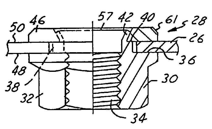
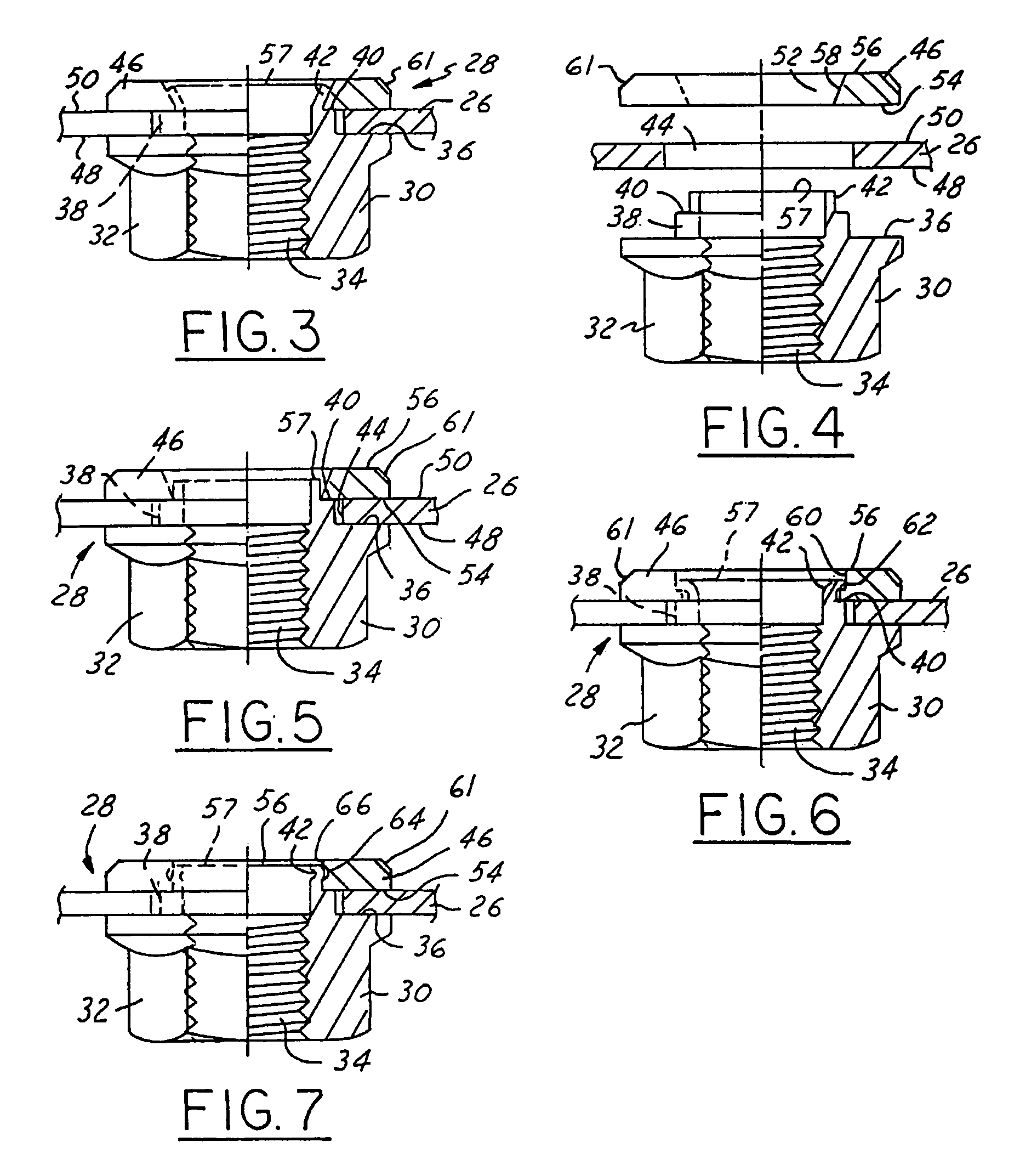
[0023]The fastener assembly 28 is more clearly shown in FIGS. 3, 4, and 5. Each fastener assembly 28 includes an internally threaded fastener 30 having a hex shaped drive section 32. The fastener 30 is commonly referred to as a captured nut. The captured nut 30 has a threaded internal aperture 34...


PUM


Abstract

A windage tray (26) has a captured nut (30) mounted to a retaining washer (46) through a central aperture (52) that has a tapered interior wall (58) which wholly retains a collar (42) of the captured nut for mounting the tray onto an internal combustion engine (10).

Description

TECHNICAL FIELD[0001]The field of this invention relates to a captured threaded nut and to a method of mounting a windage tray in an oil pan under an engine.BACKGROUND OF THE DISCLOSURE[0002]The internal combustion engine is a highly popular and developed machine. Great strides have been made to make internal combustion engines powerful, reliable, durable, and fuel efficient. One relatively recent development is the introduction of a windage tray that sits above the oil pan and below the crankshaft. The windage tray provides a splash barrier between the oil in the oil pan and the crank shaft. A rapidly rotating crankshaft may be slowed down by excess splash of oil which may rob the engine of horsepower. The windage tray also reduces frothing of the oil by the crank shaft and crank arms to reduce any air intake into the oil pump. Many windage trays are mounted on the underside of the engine block via bolt studs and nuts independent of the oil pan mounting. During engine assembly, the...

Claims


Application Information

Patent Timeline
IPC IPC(8): F01M11/00F16B37/04F16B37/06
CPCF01M11/0004F16B37/065F01M2011/0033
Inventor FENECH, CHRIS
Owner GENERAL FASTENERS
Why Eureka
Try Eureka