Control device of internal combustion engine

a control device and internal combustion engine technology, applied in the direction of electric control, ignition automatic control, machines/engines, etc., can solve the problems of preventing the realization of the and achieve the effect of improving the activation performance of the catalyst, excellent drivability, and early activation of the catalys

Inactive Publication Date: 2005-08-23
DENSO CORP
View PDF2 Cites 20 Cited by
  • Summary
  • Abstract
  • Description
  • Claims
  • Application Information

AI Technical Summary

Benefits of technology

[0007]An object of the present invention is to provide a control device of an internal combustion engine in which excellent drivability is kept and early activation of a catalyst can be realized.
[0009]According to this structure, the air-fuel ratio amplitude amount in the air-fuel ratio dither control is calculated based on the requested torque, the MBT estimated torque, and the spark timing retard limit estimated torque in each case. Thus, the air-fuel ratio dither control can be realized while making the most of the range in which the angle advance and the angle delay of the ignition timing in each case are possible, that is, the range in which the torque can be operated. Accordingly, for example, at the activation of the catalyst, the activation performance can be exhibited to the utmost extent. As a result, while the excellent drivability is kept, the early activation of the catalyst can be realized. In this case, as compared with the related art in which the air-fuel ratio dither control is performed with the previously determined amplitude amount, the catalyst activation performance is improved. Besides, even if the operation state of the internal combustion engine is changed, that can be handled, and accordingly, it is not necessary to adjust the air-fuel ratio amplitude amount in expectation of various conditions, and the number of adjusting steps can be reduced.

Problems solved by technology

This has been an obstruction to the realization of the early activation of the catalyst.

Method used


Image

  • Control device of internal combustion engine
  • Control device of internal combustion engine
  • Control device of internal combustion engine

Examples


first embodiment

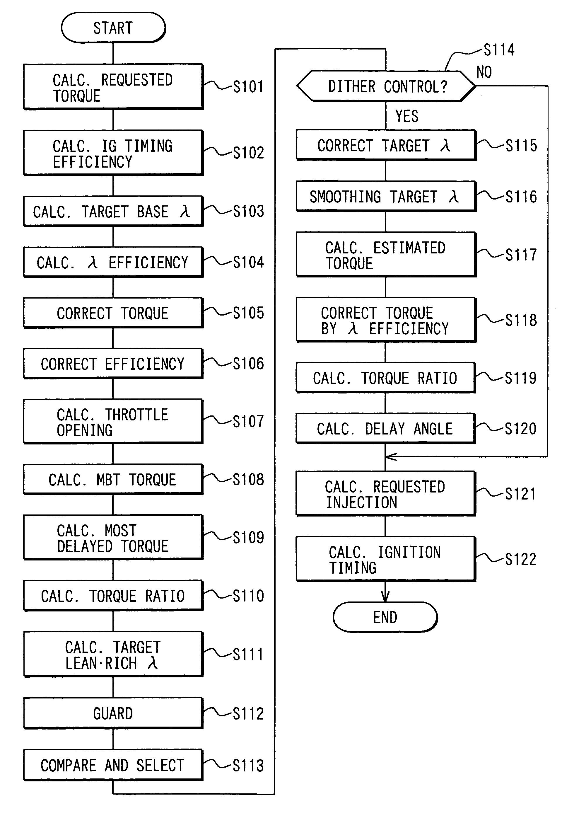
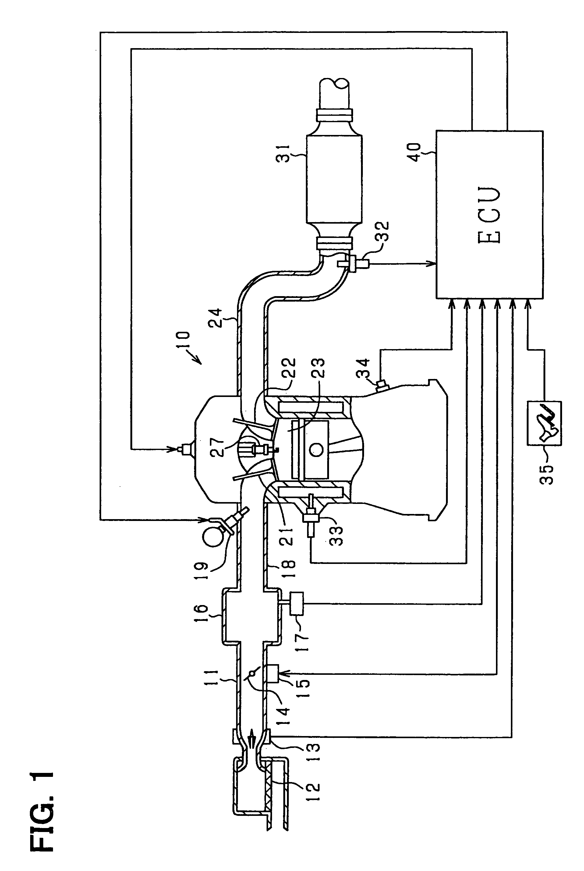
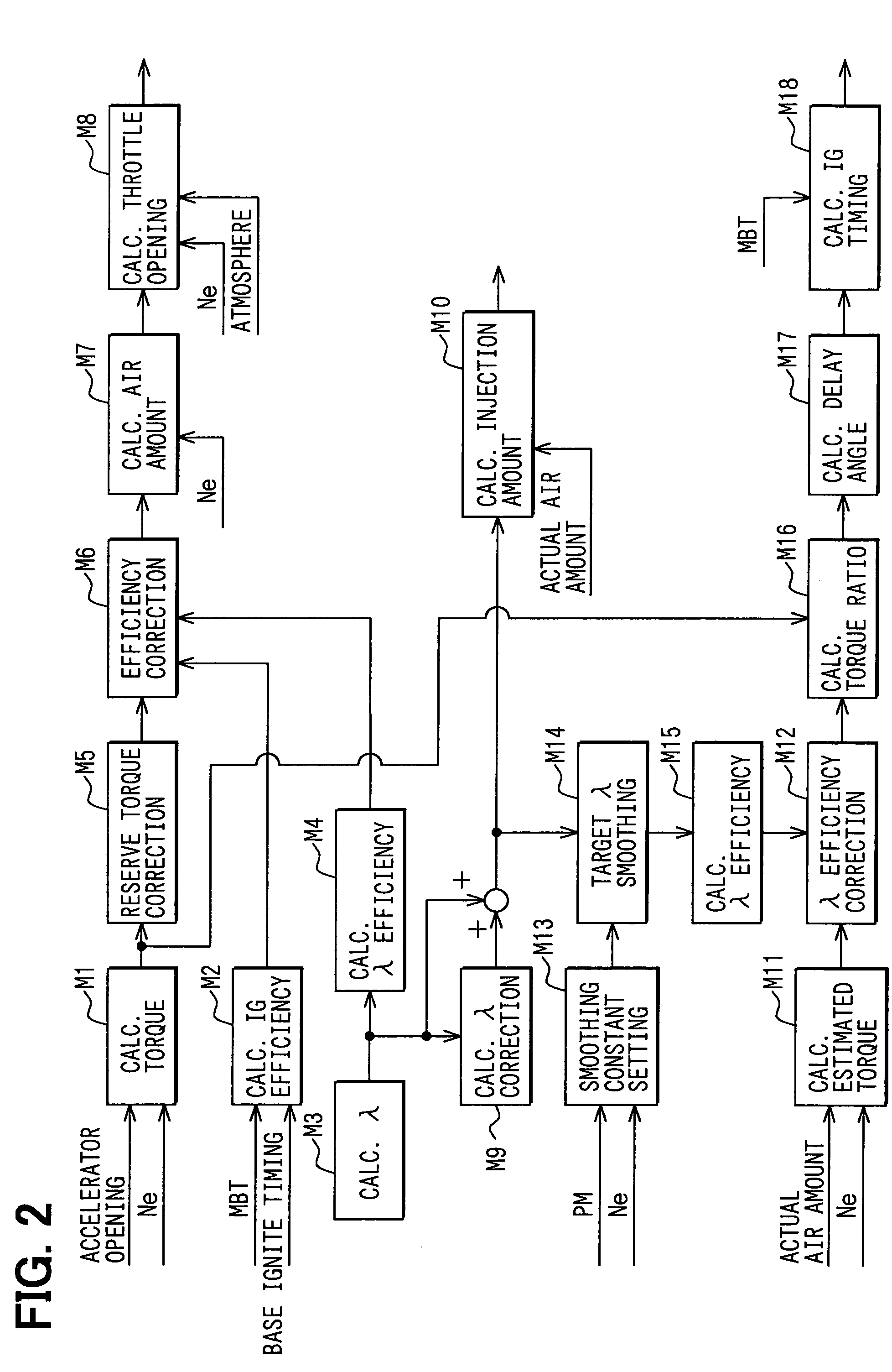
[0032]Hereinafter, a first embodiment of the present invention will be described with reference to the drawings. In this embodiment, an engine control system is configured for an on-board multi-cylinder gasoline engine as an internal combustion engine. In the control system, an electronic control unit (hereinafter referred to as an ECU) is a main part, and the control of a fuel injection amount, the control of an ignition timing and the like are performed. First, the whole rough structure of the engine control system will be described with reference to FIG. 1.

[0033]In an engine 10 shown in FIG. 1, an air cleaner 12 is provided at the most upstream part of an intake pipe 11, and an air flow meter 13 for detecting an intake air amount is provided at the downstream side of the air cleaner 12. A throttle valve 14 whose opening degree is adjusted by a throttle actuator 15 such as a DC motor is provided at the downstream side of the air flow meter 13. The opening degree (throttle opening ...

second embodiment

[0079]In this embodiment, in order to improve the controllability of air-fuel ratio dither control, under a condition that individual cylinder air-fuel ratios are uniformed, that is, variations in air-fuel ratios between cylinders are removed, the practice of the air-fuel ratio dither control is permitted. In the following, a description will be given mainly to a difference from the first embodiment, and common members are denoted by the same numbers and their description will be simplified.

[0080]FIG. 10 is a schematic view showing a main structure in this embodiment. In FIG. 10, an engine 10 is a four-cylinder engine. An exhaust pipe 24 includes manifold parts 24a connected to respective cylinders, and an exhaust collection part 24b in which the respective manifold parts 24a are collected. An air-fuel ratio sensor (A / F sensor) 32 is provided in the exhaust collection part 24b.

[0081]Besides, FIG. 10 shows individual functional blocks in a structure relating to air-fuel ratio F / B (f...


PUM


Abstract

A catalyst for purifying exhaust gas is provided in an exhaust pipe of an engine. When air-fuel ratio dither control is performed, an ECU calculates a requested torque to be generated by combustion of the engine based on an accelerator opening angle or the like operated by a driver. An MBT estimated torque corresponding to MBT (Minimum advance for the Best Torque) in each case is calculated, and a spark timing retard limit estimated torque corresponding to a spark timing retard limit in each case is calculated. An air-fuel ratio amplitude amount in the air-fuel ratio dither control is calculated based on the calculated requested torque, the MBT estimated torque, and the spark timing retard limit estimated torque. An early activation of a catalyst is realized.

Description

CROSS-REFERENCE TO RELATED APPLICATION[0001]This application is based on Japanese Patent Applications No. 2003-392060 filed on Nov. 21, 2003, and No. 2004-12781 filed on Jan. 21, 2004, the disclosures of which are incorporated herein by reference.FIELD OF THE INVENTION[0002]The present invention relates to a control device of an internal combustion engine.BACKGROUND OF THE INVENTION[0003]Conventionally, there is disclosed a technique in which a catalyst for purifying exhaust gas is installed in an exhaust pipe of an internal combustion engine. In order to activate the catalyst at an early stage immediately after the start of the internal combustion engine, a fuel injection amount is increased / decreased for every combustion, and an air-fuel ratio is oscillated between a rich side and a lean side with respect to the stoichiometric air-fuel ratio (for example, see JP-A-4-308311). That is, the air-fuel ratio is oscillated between the rich side and the lean side, so that rich combustion ...

Claims


Application Information

Patent Timeline
Patent Type & Authority Patents(United States)
IPC IPC(8): F02D37/00F02D41/14F02D37/02F02D11/10F02D41/34F02P5/15F01N3/20F01N3/24F02D41/00F02D41/02F02D41/04F02D41/20F02D41/36F02D45/00
CPCF02D11/105F02D37/02F02D41/0085F02D41/025F02D41/1408F02D41/1454F02D41/1456F02D2200/1004F02D2250/18Y02T10/26Y02T10/12
Inventor ICHIHARA, HIDEAKIIIDA, HISASHIIKEMOTO, NORIAKI
Owner DENSO CORP
Why Eureka
Try Eureka