Fluid delivery system and method

a technology of fluid delivery system and method, applied in the direction of volume metering, process and machine control, instruments, etc., can solve the problems of restricting their use in the medical field, stroke or death,

Inactive Publication Date: 2005-08-23
INTEGRATED SENSING SYST INC
View PDF3 Cites 136 Cited by
  • Summary
  • Abstract
  • Description
  • Claims
  • Application Information

AI Technical Summary

Benefits of technology

[0010]The present invention provides a fluid delivery system capable of delivering a precise amount of fluid, such as a fluid required for medical treatment, while also monitoring certain characteristics or properties of the fluid so that the correct fluid is safely delivered to its intended destination. In a preferred embodiment, the system makes use of a flow sensor of the type disclosed in U.S. Pat. No. 6,477,901 to Tadigadapa et al., wherein a micromachined resonating tube operates on the basis of the Coriolis effect to sense mass flow and density of a flowing fluid.

Problems solved by technology

However, their high cost and general requirements for relatively high flow rates have restricted their use in the medical field.
It is well known that trapped gas bubbles in the blood stream can lead to stroke or death.

Method used


Image

  • Fluid delivery system and method
  • Fluid delivery system and method
  • Fluid delivery system and method

Examples


Embodiment Construction

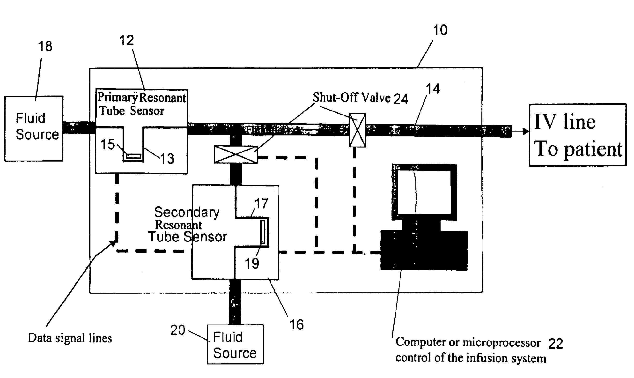
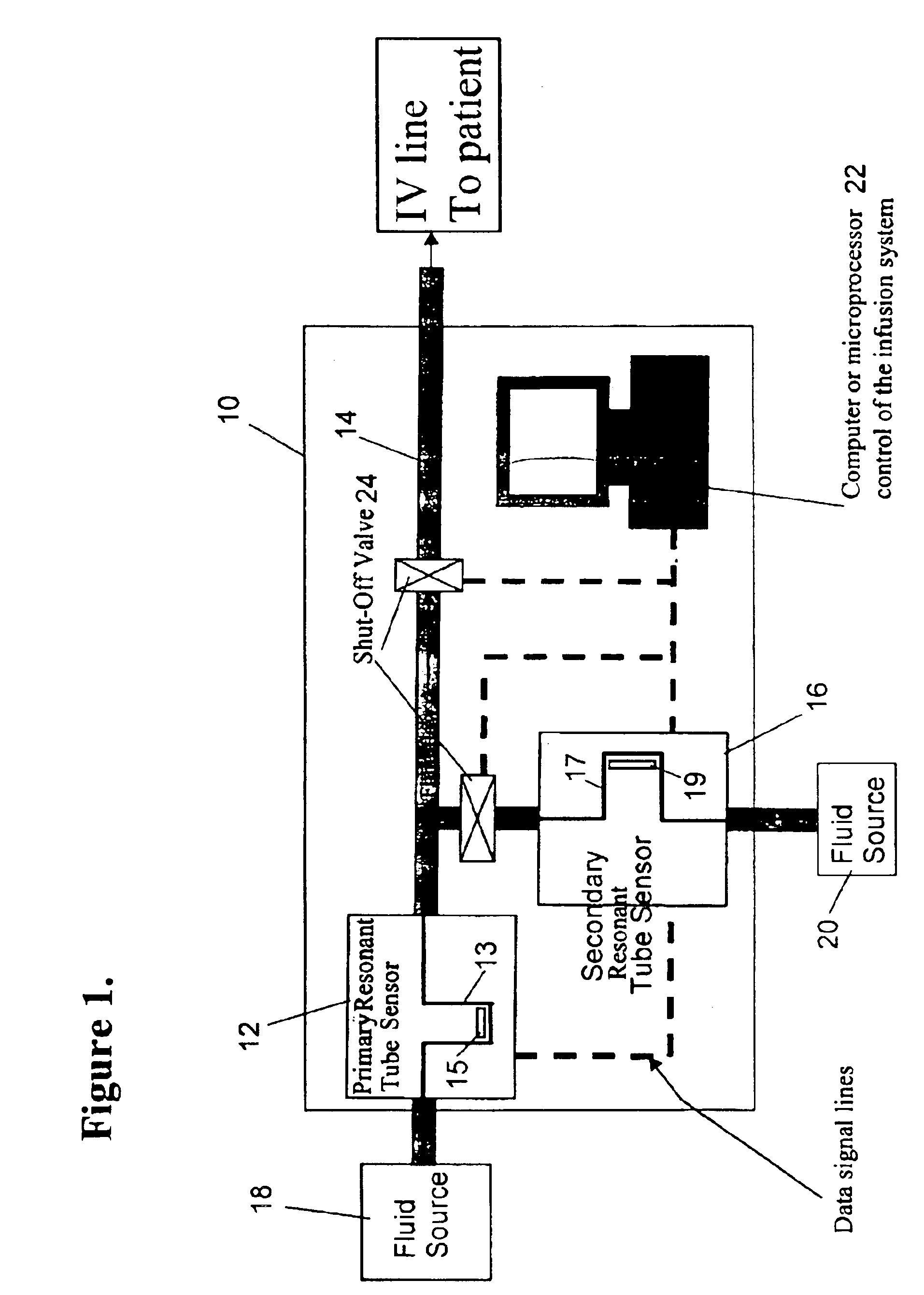
[0019]With reference to FIG. 1, a fluid delivery system 10 is shown that utilizes a primary flow sensor 12 through which a fluid flows for delivery through a tube 14 to a patient, and a secondary flow sensor 16 through which a second fluid, such as a medication, flows for infusion into the primary fluid flow. The primary and secondary fluids are represented as flowing from primary and secondary fluid sources 18 and 20, respectively, to the flow sensors 12 and 16. The tube 14 may be an IV tube used to administer a medication intravenously, though the invention is also suitable for use with other methods of drug injection, such as intra-arterial, subcutaneous, intramuscular (IM), intraperitoneal (IP) and intrathecal.

[0020]According to a preferred aspect of this invention, each flow sensor 12 and 16 comprises a tube that serves as a conduit through which its respective fluid flows, with a U-shaped freestanding portion 13 and 17 of each tube being vibrated at resonance in a manner that ...


PUM


Abstract

A fluid delivery system capable of delivering a precise amount of fluid and monitor certain properties of the fluid so that the correct fluid is safely delivered to its intended destination. The system makes use of a flow sensor comprising a freestanding tube portion vibrated at a resonant frequency, wherein the resonant frequency corresponds to the density of the fluid flowing through the tube portion and the tube portion exhibits a degree of twist that varies with the mass flow rate of the fluid flowing therethrough. Movement of the tube portion is then sensed to produce a first output signal corresponding to the fluid density and a second output signal corresponding to the mass flow rate. The system is also equipped to measure elapsed time and to stop fluid flow in response to either of the first and second output signals.

Description

CROSS REFERENCE TO RELATED APPLICATIONS[0001]This application claims the benefit of U.S. Provisional Application Ser. No. 60 / 358,360, filed Feb. 22, 2002, and U.S. Provisional Application Ser. No. 60 / 399,572, filed Jul. 30, 2002.BACKGROUND OF INVENTION[0002]1. Field of the Invention[0003]The present invention generally relates to fluid handling devices, their uses and operation. More particularly, this invention relates to a fluid delivery system and method that utilizes a resonating tube to deliver a fluid and monitor multiple parameters of the delivered fluid.[0004]2. Description of the Related Art[0005]Infusion therapy generally involves the administration of a medication to a subject using intravenous (IV), subcutaneous and epidural routes. A wide variety of fluid infusion pumps have been developed over the years that are capable of delivering a precise amount of medication at a controlled rate. Such pumps include elastomeric, gravity fed, syringe, electrical and mechanical pump...

Claims


Application Information

Patent Timeline
Patent Type & Authority Patents(United States)
IPC IPC(8): A61M5/168A61M5/36G01F1/84G01F1/76G01F13/00A61M5/142
CPCA61M5/16827A61M5/365G01F1/8445G01F1/8472G01F13/006A61M5/142A61M5/16831A61M2205/0244A61M2230/201Y10T137/212
Inventor SPARKS, DOUGLAS RAY
Owner INTEGRATED SENSING SYST INC
Why Eureka
Try Eureka