
Twist contact for electrical connector

a technology of electrical connectors and contacts, applied in the direction of coupling device connections, identification means, instruments, etc., can solve the problems of solder ball, occupying a large space, and arranging so many contacts in such limited area, so as to improve transmission, increase the contacting area, and simplify the configuration

Inactive Publication Date: 2005-08-23
HON HAI PRECISION IND CO LTD
View PDF7 Cites 49 Cited by
  • Summary
  • Abstract
  • Description
  • Claims
  • Application Information

AI Technical Summary

Benefits of technology

[0007]Accordingly, an object of the present invention is to provide a contact for use in an electrical connector. It will not only provide reliable cooperation between the contact and the solder ball, but also come into being a simple configuration. Furthermore, for high density connector, it will also provide enough space to arrange more contacts in said housing to meet the needs of high speed signal transmission. The present invention is to provide a type of contact with furcated contact portion, which can increase the contacting area for better transmission.

Problems solved by technology

So, it will get some problems to arrange so many contacts in such limited area.
However, as the contact portion doesn't extend out of the housing, the solder ball must be configured to enter into the slot and take up huge room.
Therefore, this type of socket doesn't meet the needs of high speed signal transmission.

Method used


Image

  • Twist contact for electrical connector
  • Twist contact for electrical connector
  • Twist contact for electrical connector

Examples


Embodiment Construction

[0014]Reference will now be made to the drawings to describe the present invention in detail.

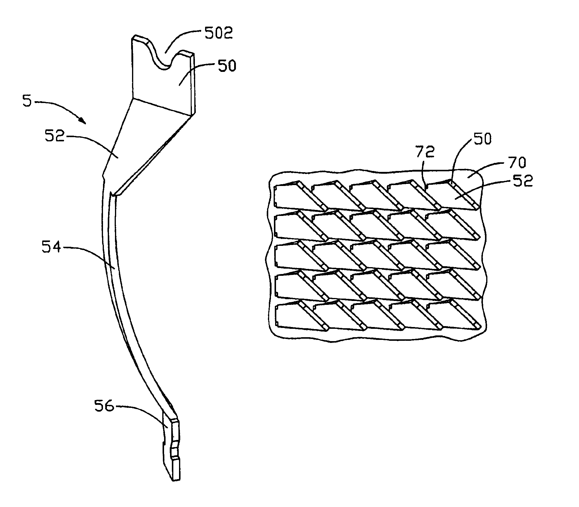
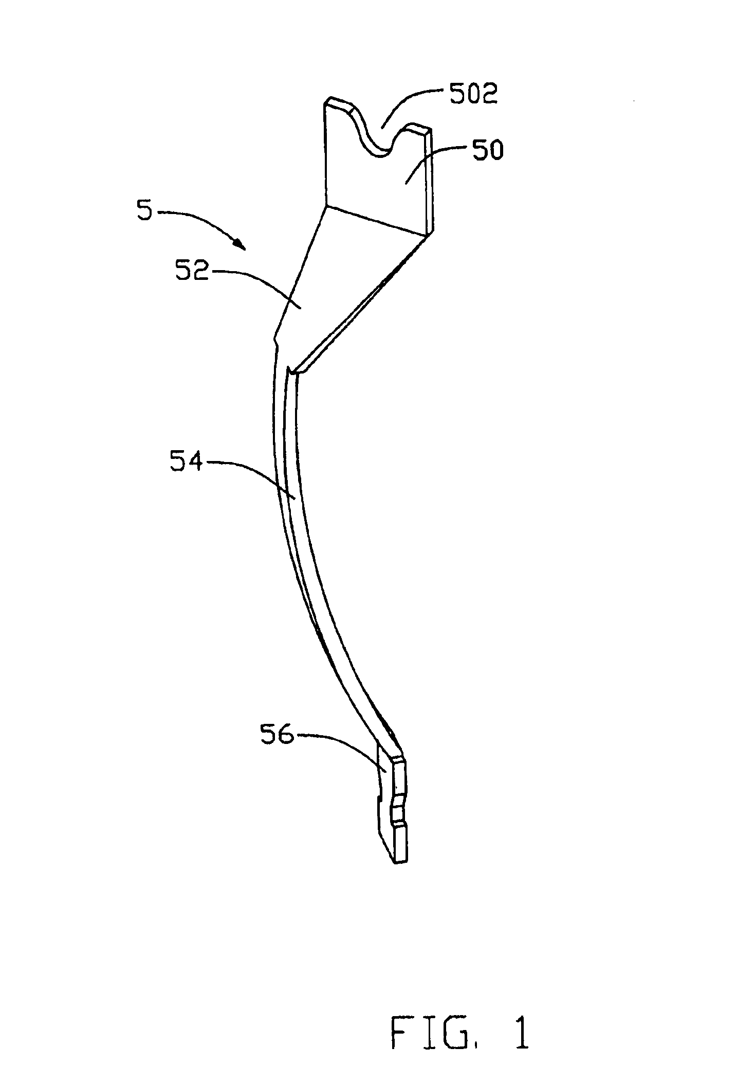
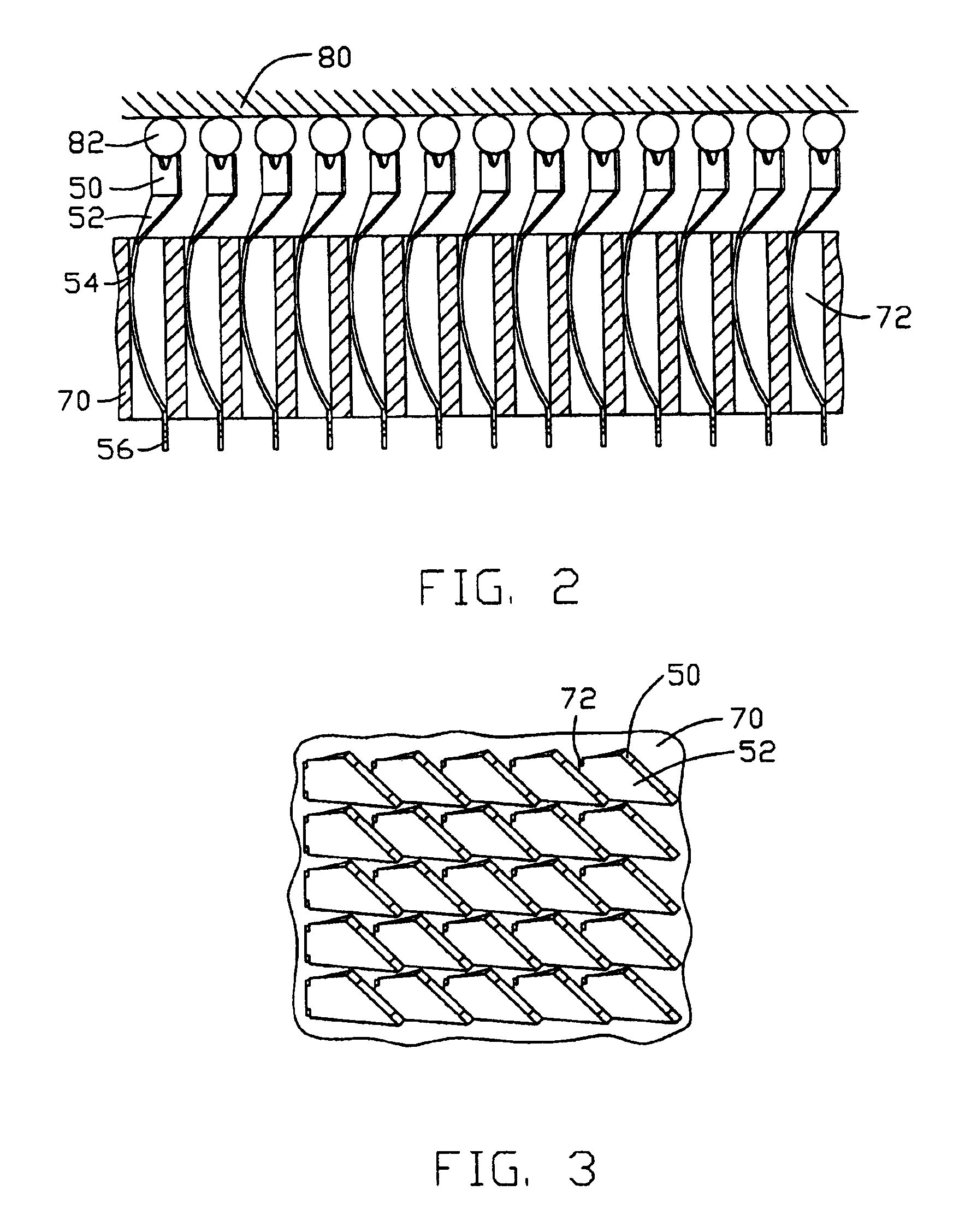
[0015]Referring to FIGS. 1, 2 and 3, a plurality of contact 5 according to present invention is arranged in slots 72 defined in an insulative housing 70 of an electrical socket (not labeled) which is adapted for connecting a chip module 80 with a Printed Circuit Board (PCB) (not shown). Each contact 5 comprises a contact portion 50 shaped in plate for contacting with corresponding solder ball 84 of the chip module 80, a tail portion 56 for being mounted on the PCB and a curving base portion 54, by which the contact 5 was hold in the slot 72 of the housing 70, located between said contact portion 50 and said tail portion 56. The contact portion 50 is formed in a Y-shape with a gap 502 defined thereon. A torsion portion 52 shaped like a triangle extends from the contact portion 50 to the curving base portion 54. While mounted in the slot 72, the contact portion 50 and the torsion portion 52 ex...


PUM

PropertyMeasurementUnit
angleaaaaaaaaaa
angleaaaaaaaaaa
angleaaaaaaaaaa

Abstract

A electrical contact, which is secured in a slot of a housing used to electrically connect a printed circuit board with a chip module comprises a tail portion mounted on the printed circuit board, a contact portion with a torsion portion based on the axis of the slot of the housing at least partly extending out of the slot contacting to the chip module and a base portion connected the tail portion with the contact portion. Thus, the space between the adjacent contacts will be improved to avoid the short circuit. Furthermore, even if the contacts are secured imprecisely, there will not be apt to form a short circuit between the adjacent contacts.

Description

BACKGROUND OF THE INVENTION[0001]1. Field of the Invention[0002]The present invention relates to a contact for use in an electrical connector, especially a contact to connect a chip module with a printed circuit board.[0003]2. Description of the Prior Art[0004]With the development of computer technology, electrical sockets each of which mainly comprises an insulating housing and a plurality of contacts are becoming more and more smaller. On the other hand, the demand of high speed signal transmission results in more and more contacts used in the sockets. So, it will get some problems to arrange so many contacts in such limited area.[0005]U.S. Pat. No. 6,142,792 discloses one conventional electrical socket. The socket comprises a dielectric housing and a plurality of contacts. The housing is formed with a plurality of slots. Each of the contacts comprises a base portion mounted in the slot, a contact portion extending from said base portion but not out of the slot for contacting a so...

Claims


Application Information

Patent Timeline
Patent Type & Authority Patents(United States)
IPC IPC(8): H01R12/30H01R12/00G06F1/16G02F1/133G09F9/00G09G3/18
CPCH01R13/2485H05K7/1069
Inventor CHEN, CHEN-JUNG
Owner HON HAI PRECISION IND CO LTD
Learn More