Wrist type blood pressure meter cuff

a blood pressure meter and wrist-type technology, applied in the field of wrist-type blood pressure meter cuffs, can solve the problems of large oppressive pressure, inconvenient use, inaccurate blood pressure measurements, etc., and achieve the effect of reducing the oppressive pressure on the non-selected artery

Inactive Publication Date: 2005-08-23
OMRON HEALTHCARE CO LTD
View PDF13 Cites 9 Cited by
  • Summary
  • Abstract
  • Description
  • Claims
  • Application Information

AI Technical Summary

Benefits of technology

[0016]In the wrist type blood pressure meter cuff, preferably, the fixing member has a structure so that the rate of area of direct contact of the fixing member at the wrist at which the non-selected artery is located is smaller than the rate of area of direct contact of the fixing member in other position of the wrist. In such configuration, the oppressing surface of the non-selected artery is smaller than other part, and oppressing pressure on the non-selected artery can be decreased.
[0017]In the wrist type blood pressure meter cuff, preferably, the fixing member has an opening in the position coinciding with the non-selected artery. In this configuration, the area of the fixing member directly contacting with the wrist surface at which the non-selected artery is located is decreased.

Problems solved by technology

In certain users, by the conventional cuff, the oppressing pressure of the fluid bag does not reach sufficiently to the arteries, and the arteries are not oppressed sufficiently, and accurate blood pressure measurements may not be obtained.
Besides, a large oppressing pressure is needed for oppressing two arteries, and the user suffers a large oppressing pressure during measurement and it is not comfortable for the user.

Method used


Image

  • Wrist type blood pressure meter cuff
  • Wrist type blood pressure meter cuff
  • Wrist type blood pressure meter cuff

Examples


embodiment 1

(Embodiment 1)

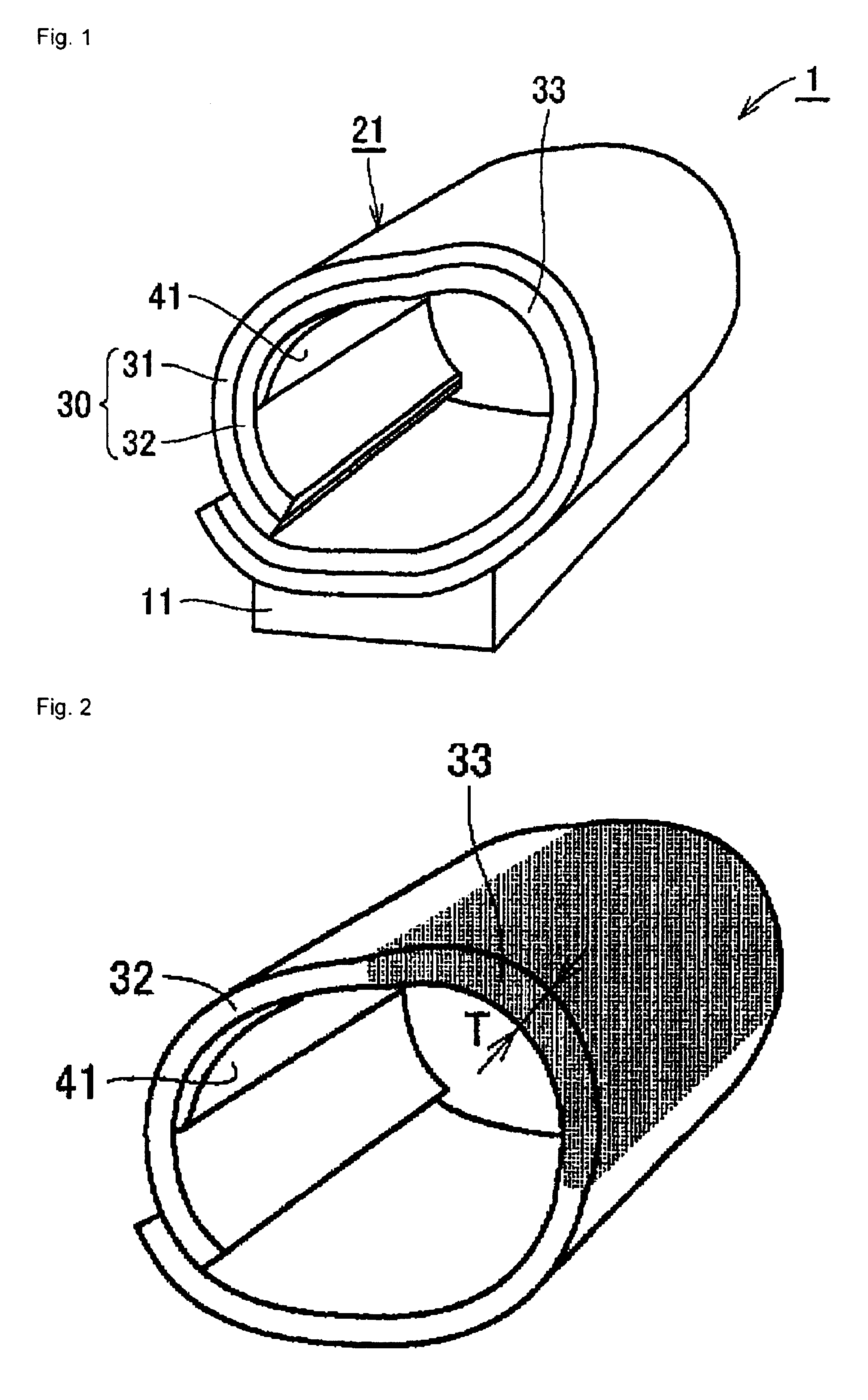
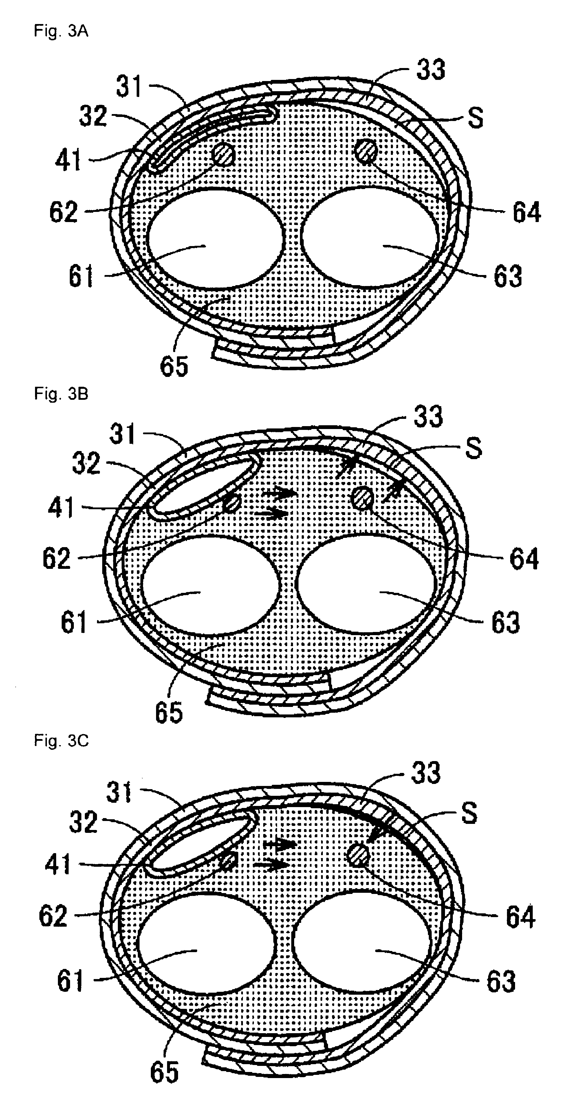
[0029]A wrist type blood pressure meter cuff in this embodiment is explained by referring to FIG. 1 to FIG. 3. FIG. 1 is a perspective view showing a structure of a wrist type blood pressure meter in this embodiment, FIG. 2 is a perspective view showing a structure of a curler of fixing member of a wrist type blood pressure meter cuff in the embodiment, and FIG. 3 is a sectional view explaining the state of use of the wrist type blood pressure meter cuff in the embodiment.

(Structure of Wrist Type Blood Pressure Meter Cuff)

[0030]A structure of a wrist type blood pressure meter cuff is explained. As shown in FIG. 1, a wrist type blood pressure meter cuff 21 is integrated with a blood pressure meter main body 11, and a blood pressure meter 1 is composed. The cuff 21 is composed of fixing member 30 including a band 31 and a curler 32, and a fluid bag 41 fixed to its inner surface. The blood pressure meter main body 11 incorporates a pump for feeding air into the fluid bag ...

embodiment 2

(Embodiment 2)

[0047]A wrist type blood pressure meter cuff in this embodiment is explained by referring to FIG. 4, and only the structure different from the foregoing embodiment is described. FIG. 4 is a sectional view explaining the state of use of the wrist type blood pressure meter cuff in this embodiment.

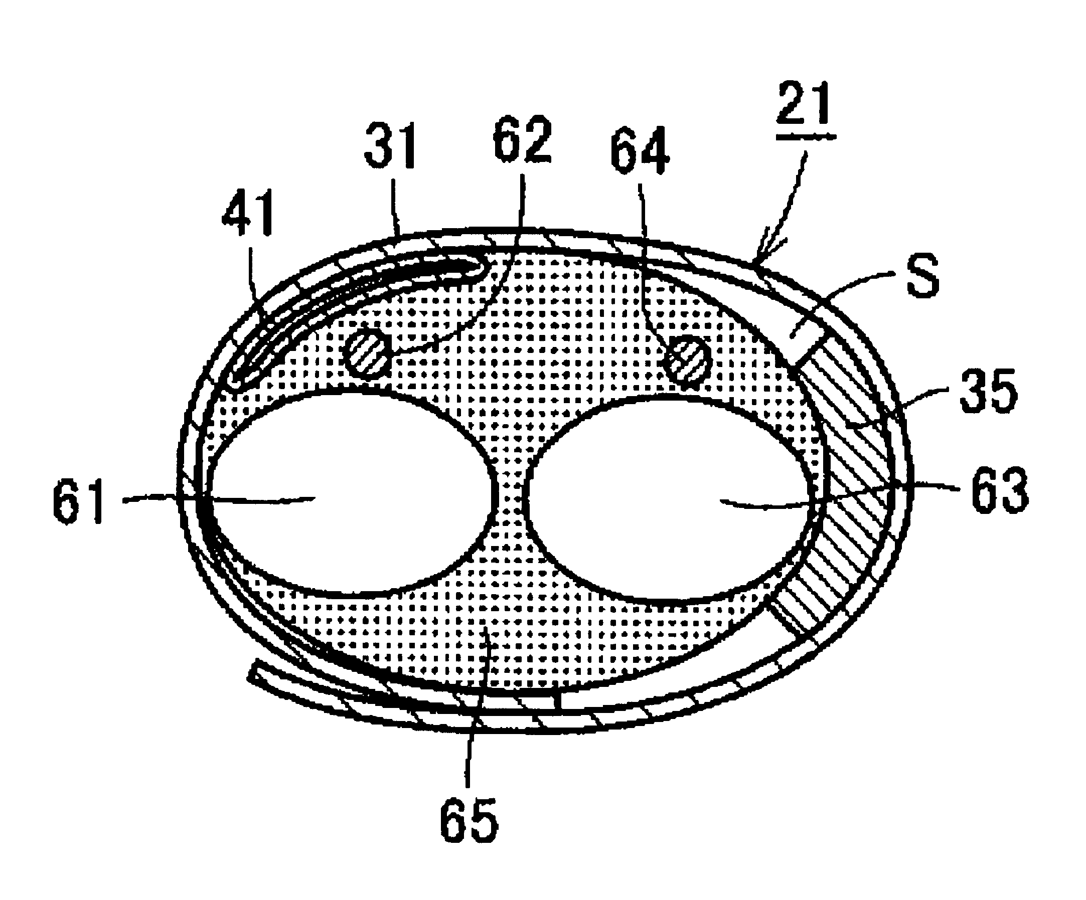
[0048]As shown in FIG. 4, in this embodiment, by a spacer 35 provided at the inner surface side of a fixing member 30, a gap S is formed between the non-selected artery 64 and the fixing member 30. The spacer 35 is composed of an elastic material such as foamed urethane, and its inner surface is formed in a C-figure along the bone 63 of the wrist 65. In this configuration, when the cuff 21 is worn, as shown in FIG. 4, the spacer 35 is properly deformed, and its inner side fits to the bone 63 of the wrist 65; and the cuff 21 can be stably fixed. At the same time, the gap S can be formed securely.

[0049]When the fluid bag 41 is inflated with air and the fluid bag 41 is expanded unt...

embodiment 3

(Embodiment 3)

[0050]A wrist type blood pressure meter cuff in this embodiment is explained by referring to FIG. 5 and FIG. 6, and only the structure different from embodiment 1 is described. FIG. 5 is a perspective view of the wrist type blood pressure meter cuff in the embodiment, and FIG. 6 is a sectional view explaining the state of use of the wrist type blood pressure meter cuff in this embodiment.

[0051]In this embodiment, a fixing device 30 has an opening 36, and the rate of area of direct contact of the fixing member 30 at the wrist 65 at which the non-selected artery is located is set smaller than the rate of area of direct contact of the fixing member 30 in other position of the wrist 65. That is, at the wrist 65 of the location of the non-selected artery, since the opening 36 is formed in the fixing member 30, the fixing member 30 contacts directly only in the area other than the opening 36, and the rate of area of direct contact of the fixing member 30 is smaller than in o...


PUM


Abstract

Provide is a wrist type blood pressure meter cuff not oppressing the non-selected artery so as to prevent its pulse waves from mixing into pulse waves of the selected artery necessary for measurement, in a cuff used in a blood pressure meter for measuring blood pressures by selecting and oppressing one artery of the wrist. A wrist type blood pressure meter cuff comprises a fluid bag for oppressing a selected artery of either radial artery or ulnar artery located at the wrist by feeding fluid inside to inflate, and a fixing member for fixing the fluid bag at the wrist. By forming a gap between the fixing member and the wrist, the oppressing pressure directly applied from the fixing member to the wrist at which the non-selected artery is located is set smaller than the oppressing pressure directly applied from the fixing member to other position of the wrist when oppressing the wrist by inflating the fluid bag. This gap is produced by a swollen part provided in the fixing member.

Description

BACKGROUND OT THE INVENTION[0001]1. Field of the Invention[0002]The present invention relates to a wrist type blood pressure meter cuff comprising a fluid bag filled with fluid such as air for oppressing a selected artery of the wrist, and a fixing member for fixing the fluid bag to the wrist.[0003]2. Description of the Prior Art[0004]The wrist on which a wrist type blood pressure meter is worn includes two arteries, the radial artery and ulnar artery, and it is general to oppress both of them when measuring the blood pressures in the wrist type blood pressure meter. However, the radial artery and ulnar artery at the wrist are somewhat deeply seated between the two bones of radius and ulna and parallel tendons. In certain users, by the conventional cuff, the oppressing pressure of the fluid bag does not reach sufficiently to the arteries, and the arteries are not oppressed sufficiently, and accurate blood pressure measurements may not be obtained. As compared with the brachial arter...

Claims


Application Information

Patent Timeline
Patent Type & Authority Patents(United States)
IPC IPC(8): A61B5/022
CPCA61B5/02233
Inventor INOUE, TOMONORISHIRASAKI, OSAMUSANO, YOSHIHIKOOHTANI, TOSHIO
Owner OMRON HEALTHCARE CO LTD
Why Eureka
Try Eureka