Electronic ballast using cut and save technology

a technology of electronic ballast and cut-and-save technology, which is applied in the direction of electrical equipment, instruments, light sources, etc., can solve the problems of low reliability, poor consistency, and reduce so as to prolong the life of the lamp tube, improve safety performance, and improve the whole efficiency of the electronic ballast

Inactive Publication Date: 2005-08-23
FEIHONG ELECTRONICS SUZHOU
View PDF18 Cites 8 Cited by
  • Summary
  • Abstract
  • Description
  • Claims
  • Application Information

AI Technical Summary

Benefits of technology

[0020]A filament is given a fixed voltage and preheated in a set time after a power supply of electronic ballast is turned ON. Since the voltage output to a lamp tube is the difference between voltages on the secondary windings of both the output transformer T1 and other transformer T2, the lamp tube voltage can remain low (e.g., less than 50 V) during the preheating of the lamp tube. After completing preheating, the control circuit can cause the lamp tube voltage to rise instantly so as to light the lamp tube. At the same time as the lighting of the lamp tube, the control circuit causes the voltage applied to the filament of the lamp tube to be removed, so that the power consumption on the filament is avoided to improve the whole efficiency of the electronic ballast. Accordingly, the present invention not only realizes the ideal starting of the electronic ballast, extends the life of the lamp tube, and achieves the energy saving purpose, but also improves safety performance. Therefore, the output voltage is less than 50 V even under the tuning ON state without a lamp tube.

Problems solved by technology

However, the facts have proved that the preheating by excessive filament current causes the premature degradation of the filament and therefore reduces the life of the lamp tube, and a reasonable filament preheating current is necessary.
By summarizing the present art conditions introduced above, the inventors have recognized the following facts: although the method is simple using a thermistor with positive temperature coefficient, due to influence of its performance, there are poor consistency and low reliability and a glow discharging phenomena is easily caused when the circuit is not properly adjusted.
In addition, due to a heat effect of the thermistor, more than 1 W of power is consumed by electronic ballasts.
By employing an IC as a driving control circuit, though there are realized powerful functions, simple adjustments, conveniently presetting preheat time, and other functions, it is difficult for a voltage output to a lamp tube to be reduced to an ideal condition due to a limited adjusting frequency (about two times), and especially for a lamp tube operated under a low tube voltage, the glow discharging phenomena occurs very easily.
Furthermore, the cost of an IC and the complexity of its peripheral circuits also prevents it from being widely used.
Therefore, the foregoing two methods cannot completely solve the problems of preheat starting and excessive tube voltage in starting.

Method used


Image

  • Electronic ballast using cut and save technology
  • Electronic ballast using cut and save technology
  • Electronic ballast using cut and save technology

Examples


Embodiment Construction

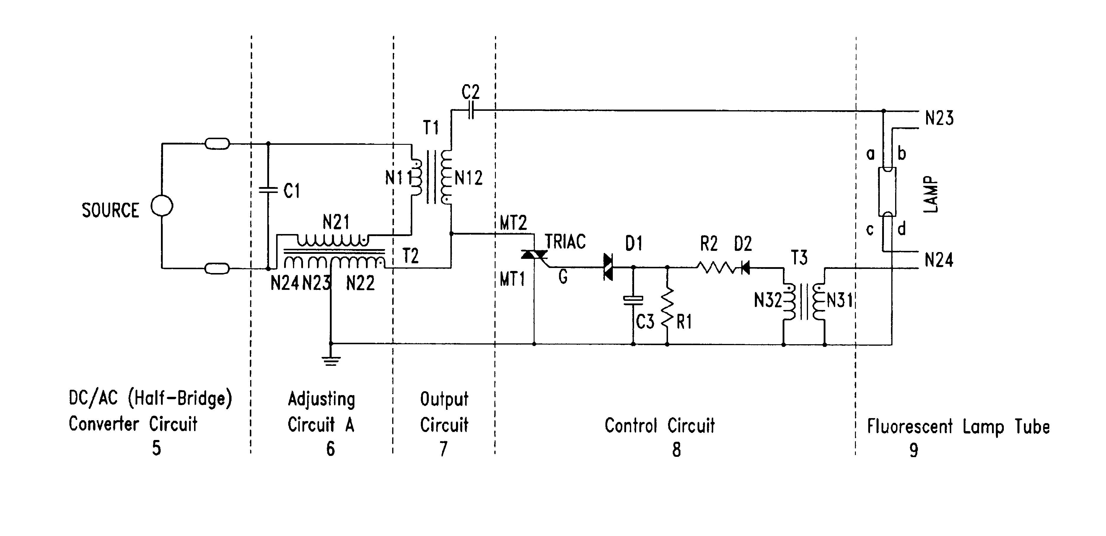
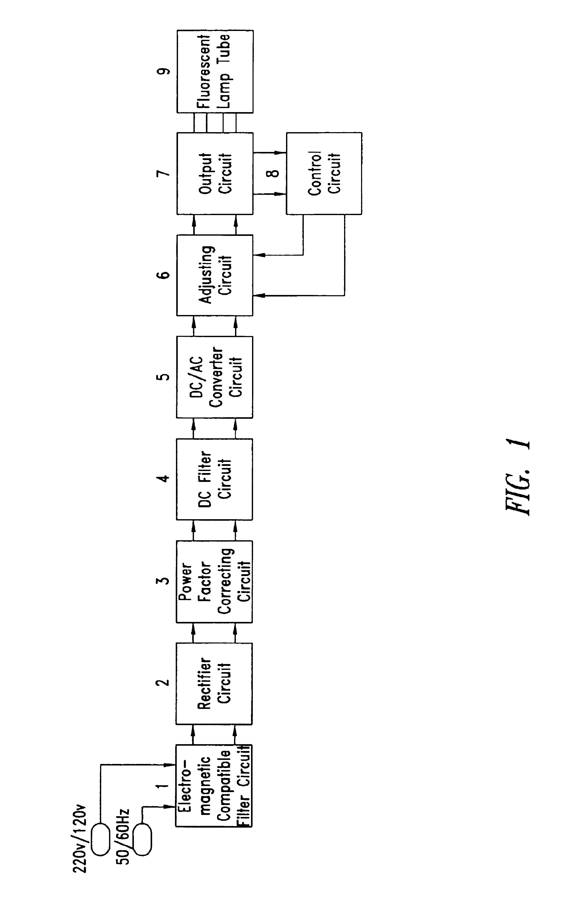
[0025]As shown in FIG. 1, an electronic ballast includes an electro-magnetic compatible filter circuit 1, a rectifier circuit 2, a power factor correcting circuit (PFC) 3, a DC filter circuit 4, a DC / AC converter circuit 5, an adjusting circuit 6, an output circuit 7, and a control circuit 8 connected successively.

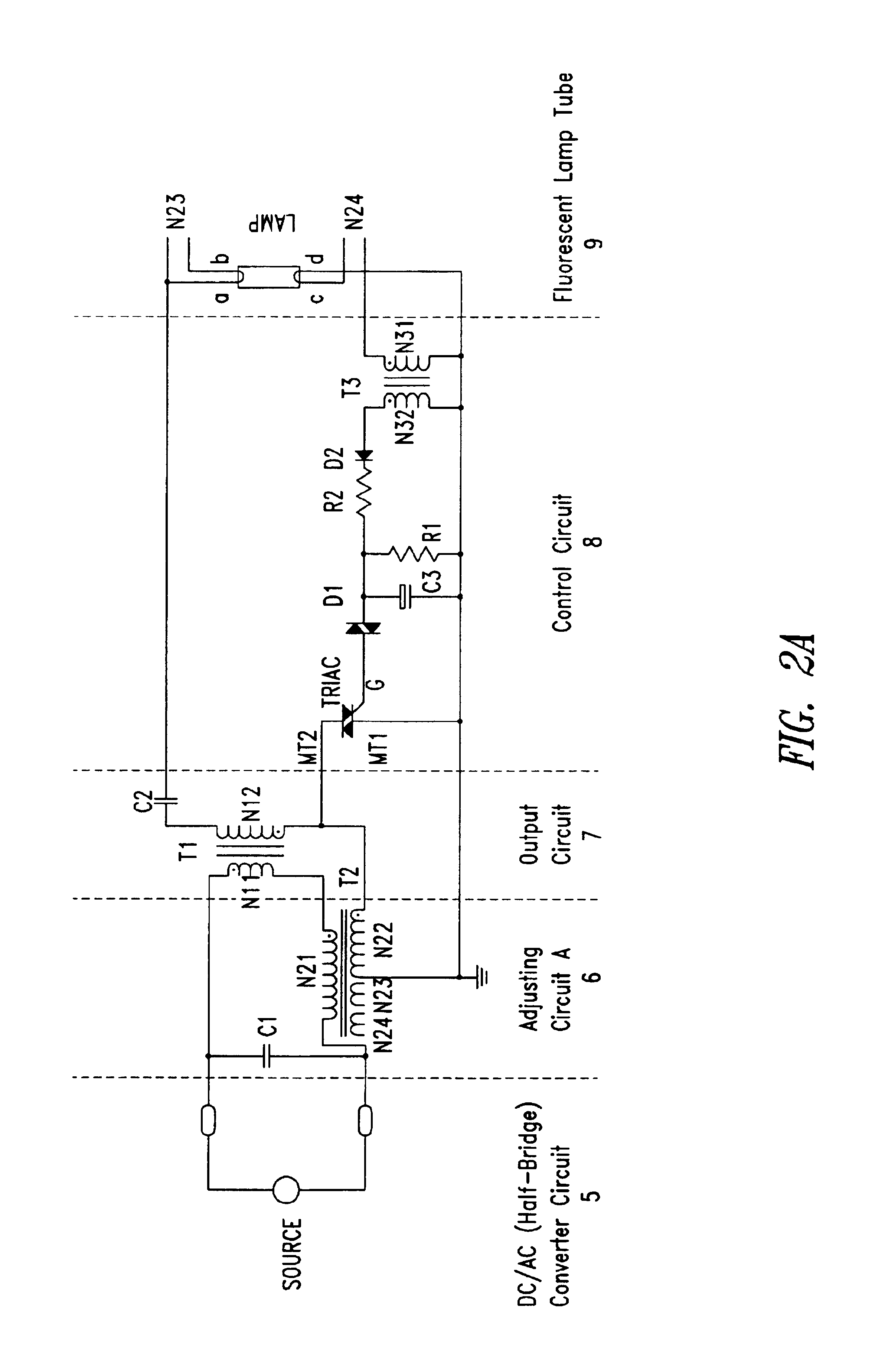
[0026]As shown in FIG. 2a, a primary winding N21 of a transformer T2 in the adjusting circuit 6 is connected in series to a primary winding N11 of a transformer T1 in the output circuit 7. In particular, the same polarity end of the primary winding N21 of the transformer T2 is connected to the different polarity end of the primary winding N11 of the transformer T1 in the output circuit 7, and both the other end of the primary winding N21 of the transformer T2 and the other end of the primary winding N11 of the transformer T1 are connected to output ends port 1 and port 2 of the DC / AC converter circuit 5 respectively, with a resonant capacitor C1 being connected between the...


PUM


Abstract

An ideal filament preheat technique in flourescence lamp is supplied by an adjusting circuit, an output circuit and a control circuit. At the filament preheating stage, an adequate preheating voltage is provided for the filament of the lamp tube, and the voltage cross over both ends of the lamp tube is reduced, thereby preventing glow current in preheating. When the preheating stage is finished and starting stage begins, the voltage between both ends of the lamp tube increases simultaneously, and then reaches a break-down voltage of the lamp tube, then the lamp tube is lit to enter a normal operation stage, the preheating voltage of the filament is cutoff under the control circuit, so as to save the filament power consumption. Therefore, the efficiency of the electronic ballast is improved, and the operation life of the flourescent lamp tube is extended.

Description

BACKGROUND OF THE INVENTION[0001]1. Field of the Invention[0002]The present invention relates to electronic ballast circuitry for fluorescent lamps.[0003]2. Description of the Related Art[0004]A fluorescent lamp is a “green” (i.e., energy-saving and / or high-efficiency) light source, and advantageously has a color-temperature which is capable of being controlled. Fluorescent lamps have been widely used in various fields and become a preferred choice of man-made light sources in daily life. When such a high efficiency and high quality light source is widely used, not only is its energy and efficiency (for example, the development towards minimization, integration, digitalization, energy saving, and high efficiency), but also its operational life, is given much attention.[0005]In the prior art, in order to increase the life of a fluorescent lamp tube, besides improving the quality of the lamp tube itself, two steps are generally performed, i.e., its filament is sufficiently preheated a...

Claims


Application Information

Patent Timeline
Patent Type & Authority Patents(United States)
IPC IPC(8): H05B41/295H05B41/298H05B41/28
CPCH05B41/295H05B41/2988
Inventor YANG, KEVIN JIANWENZENG, HAORANMAO, SONGLING
Owner FEIHONG ELECTRONICS SUZHOU
Why Eureka
Try Eureka