Optical system

Inactive Publication Date: 2005-08-23
GIVEN IMAGING LTD
View PDF39 Cites 112 Cited by
  • Summary
  • Abstract
  • Description
  • Claims
  • Application Information

AI Technical Summary

Benefits of technology

[0012]The present invention provides an optical system for illuminating and viewing a target in which an illumination element and a

Problems solved by technology

More complex optical systems include automated processors as means for receiving the light remitted from a viewed target.
In vehicles such as submarines or trains travelling in a dark tunnel, this may be a perilous task.
A frequent problem encountered in ha

Method used


Image

  • Optical system
  • Optical system
  • Optical system

Examples


Embodiment Construction

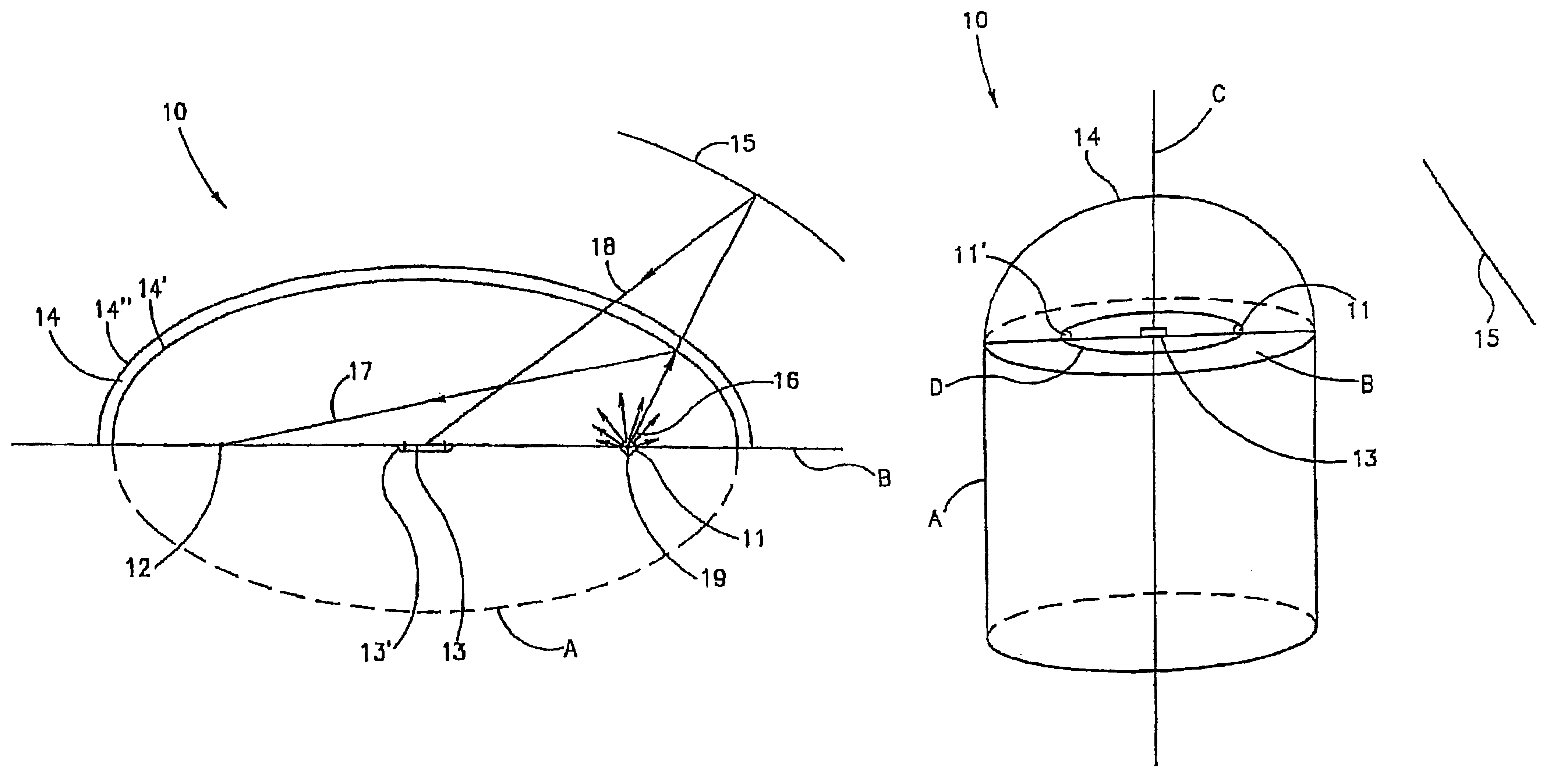
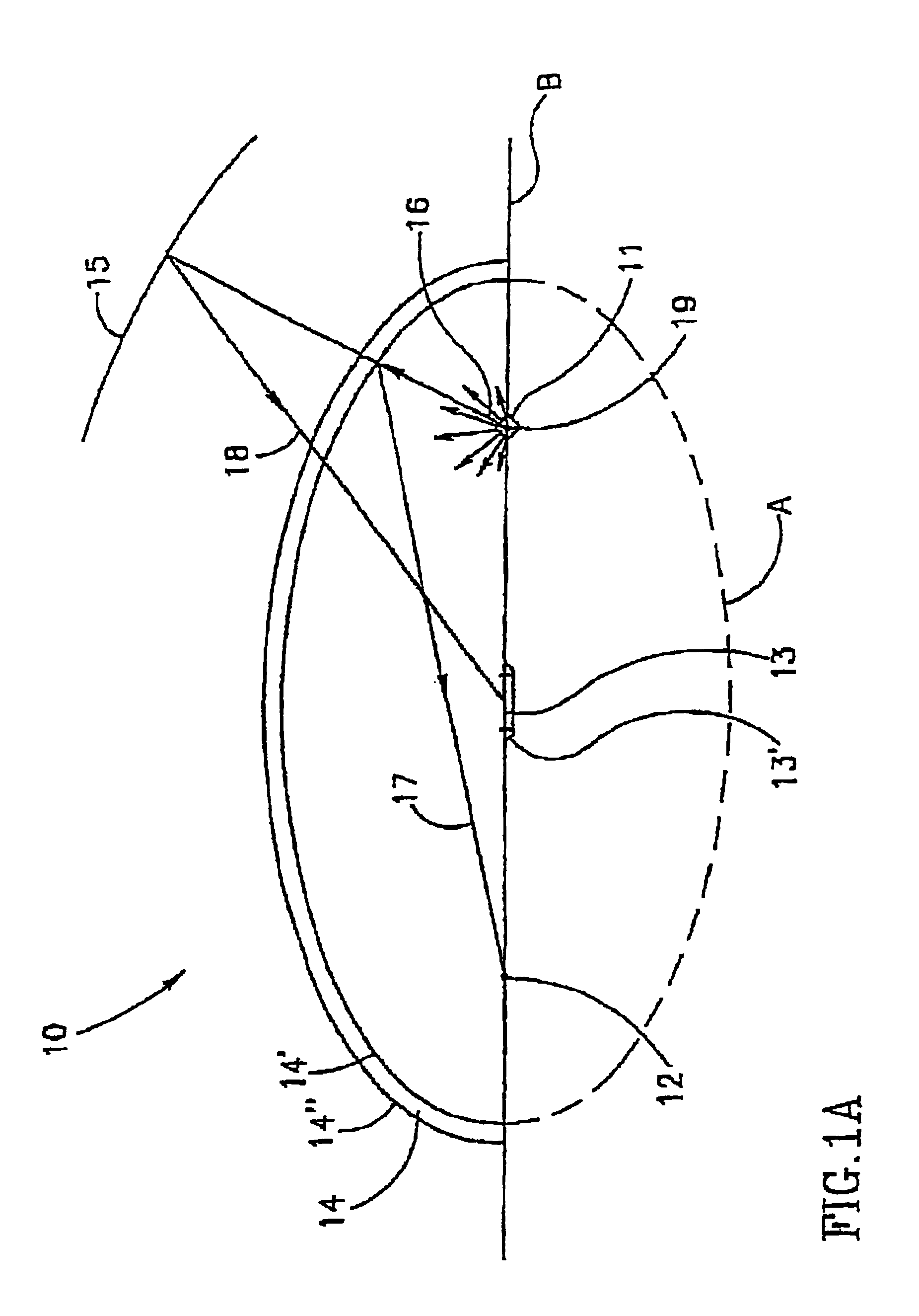
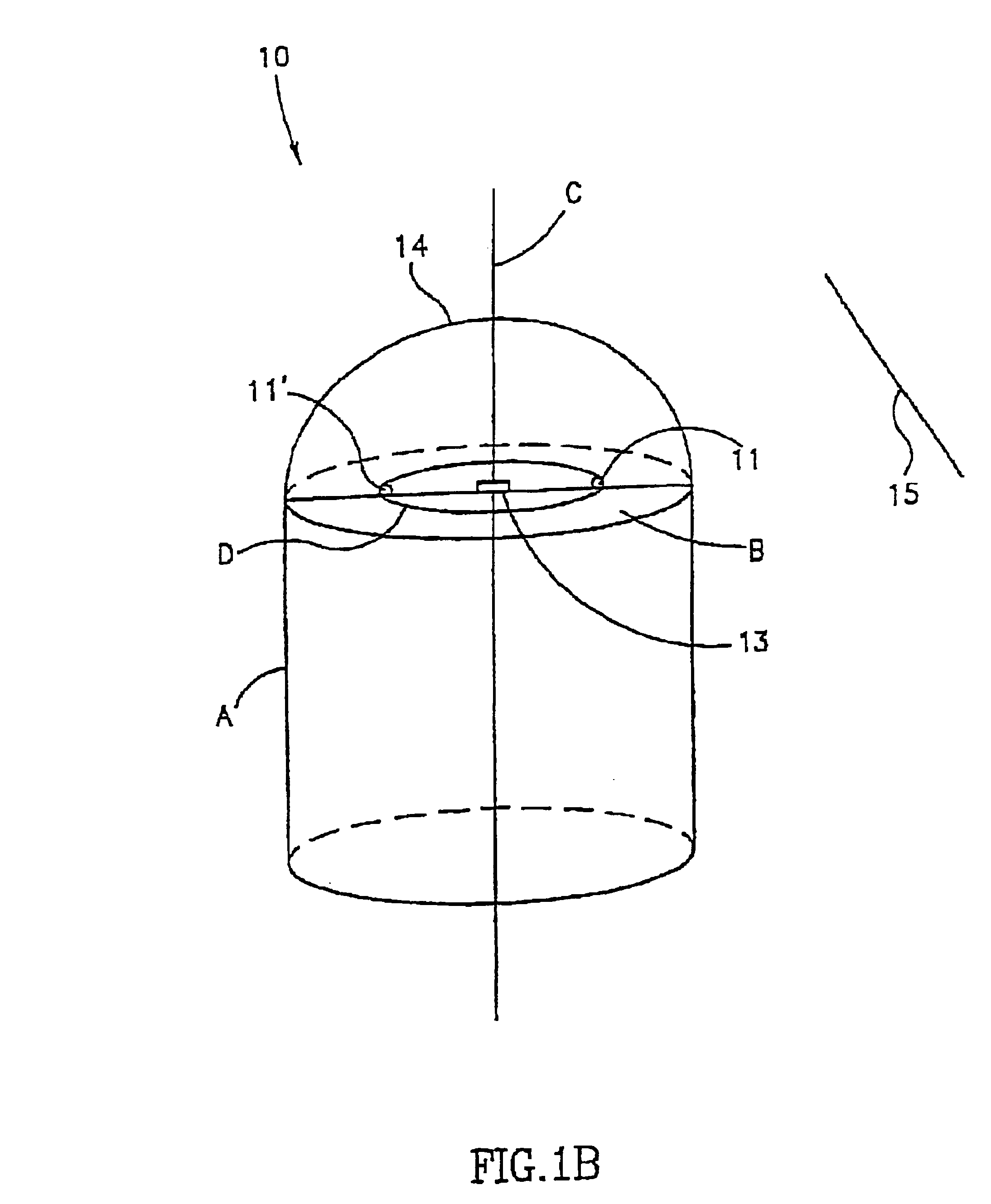
[0023]The present invention relates to an optical system based on geometrically positioning both illumination elements and means for receiving light behind a single optical window, such that internally reflected light from the optical window will not be incident on the receiving means.

[0024]The optical window, which is made of any suitable glass or plastic, can be viewed as being assembled from infinitesimal level surfaces, each level surface internally reflecting an illumination ray incident on it at a reflection angle equal to the angle of incidence. The level surfaces are angled to each other such that reflected illumination rays are always converged at a single known point.

[0025]This assembly can result in a shape having focal points (for example, an ellipse) and an optical window thus assembled would have the optical property that light rays emitted from one focal point, which are internally reflected, will be propagated to the second focal point. In a three dimensional shape (...


PUM


Abstract

The present invention provides an optical system for illuminating and viewing a target in which an illumination element and a receiving means are disposed behind a single optical window, and which obtains data essentially free of backscatter and stray light. The optical window of the optical system is configured such that it defines a shape having at least one focal curve, i.e., an ellipsoid shaped dome. The illumination element and the receiving means are geometrically positioned on the focal curve plane or in proximity of the focal curve plane, such that, when illuminating, rays from the illumination elements, that are internally reflected from the optical window, will not be incident on the receiving means.

Description

CROSS REFERENCE TO RELATED APPLICATIONS[0001]This application is a Continuation of U.S. patent application Ser. No. 10 / 009,837, filed Aug. 22, 2002, entitled “AN OPTICAL SYSTEM”, which claims benefit of PCT Application no. PCT / IL00 / 00349, filed 15 Jun. 2000, which claims benefit from Israeli Patent Application no. IL 130486, filed 15 Jun. 1999, all of which are incorporated in their entirety herein by reference.FIELD OF THE INVENTION[0002]The present invention relates to an optical system for illuminating and viewing a target.BACKGROUND OF THE INVENTION[0003]An optical system for illuminating and viewing a target, which comprises a target, a source of illumination of the target and means for receiving the light remitted from the target, can be defined by an illumination axis and optical axis that converge at the target.[0004]Such an optical system may be as simple as an operator of an illumination source viewing a target, wherein the operator embodies the means for receiving the lig...

Claims


Application Information

Patent Timeline
IPC IPC(8): A61B1/05A61B1/06G02B27/00G02B23/24G02B17/00A61B1/31A61B1/00A61B1/04A61B5/07G02B23/26H04N7/18
CPCA61B1/00096A61B1/041G02B17/00G02B23/2407G02B27/0018H04N7/18A61B1/051A61B1/0661A61B1/31
Inventor KISLEV, HANOCHGLUKHOVSKY, ARKADYMERON, GAVRIELIDDAN, GAVRIEL J.
Owner GIVEN IMAGING LTD
Why Eureka
Try Eureka