Device and method for testing out-band relative spectral responsivity of solar blind ultraviolet image intensifier
A technology like intensifier and spectral response, applied in testing optical performance and other directions, can solve the problems of low out-of-band response, inability to accurately characterize solar-blind UV ICCD spectral response characteristics, inability to accurately test out-of-band relative spectral responsivity, etc. The effect of increasing the dynamic range
- Summary
- Abstract
- Description
- Claims
- Application Information
AI Technical Summary
Problems solved by technology
Method used
Image
Examples
specific Embodiment approach 1
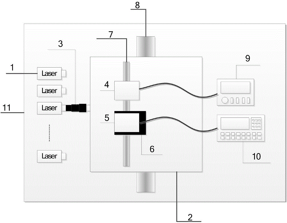
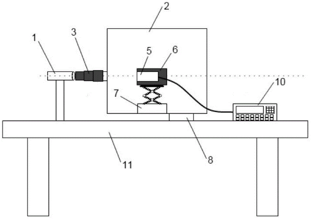
[0017] Specific implementation mode 1. Combination figure 1 and figure 2 To illustrate this embodiment, the solar-blind ultraviolet image intensifier out-of-band relative spectral responsivity testing device includes:
[0018] The light source 1 is a series of high-stable mW-level laser diodes, which are placed horizontally along the same height in order of wavelength; the dark box 2 is located in front of the light source 1, and a light entrance is provided on the side, which can avoid the test from being affected by ambient stray light; The retractable shielding cover 3 is located between the light entrance and the light source 1, and is used to shield the ambient stray light near the light source 1 from entering the dark box; the trap detector 4 is located inside the dark box 2, and is used to detect The output photocurrent of the light source 1; the shielding box 6, located inside the dark box 2, is used to hold the image intensifier to be measured, and effectively elect...
specific Embodiment approach 2
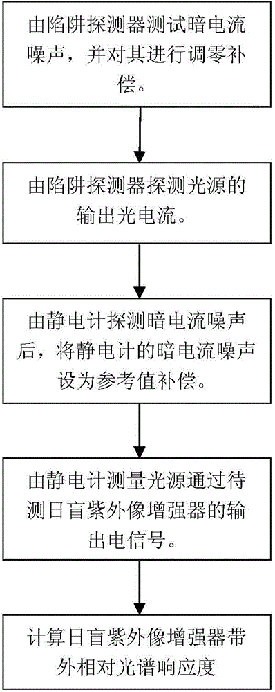
[0021] Specific embodiment two, combine image 3 Describe this embodiment, this embodiment is the testing method of the out-of-band relative spectral responsivity testing device of the sun-blind ultraviolet image intensifier described in the specific embodiment one, comprising the following steps:
[0022] 1. The dark current noise is tested by the trap detector 4 and zero-adjusted for compensation. This step is specifically as follows: close the light entrance of the dark box 2 so that no light enters on the trap detector 4, measure the output electrical signal of the trap detector 4 as dark current noise, and convert the trap detector at this time 4. Zeroing to compensate the dark current noise; detecting the output photocurrent of the light source 1 by the trap detector 4. This step specifically includes: adjusting the guide rail 8 of the dark box so that the light source 1 is aligned with the light entrance of the dark box 2 , and adjusting the precision displacement plat...
PUM
| Property | Measurement | Unit |
|---|---|---|
| Sensitivity | aaaaa | aaaaa |
Abstract
Description
Claims
Application Information
 - R&D
- Intellectual Property
- Life Sciences
- Materials
- Tech Scout
- Unparalleled Data Quality
- Higher Quality Content
- 60% Fewer Hallucinations
Browse by: Latest US Patents, China's latest patents, Technical Efficacy Thesaurus, Application Domain, Technology Topic, Popular Technical Reports.
© 2025 PatSnap. All rights reserved.Legal|Privacy policy|Modern Slavery Act Transparency Statement|Sitemap|About US| Contact US: help@patsnap.com


